
Task 22: Exporting Photo Data
The Output (Photo Data) command allows you to create the Gerber files for fabricating printed circuit boards. In this task, you will output photo data in RS-274X format.
- Open the design Design7.pdes.
- On the eCADSTAR PCB Editor ribbon, select Manufacture > Manufacture Output > Photo Data. The Output (Photo Data) dialog is displayed.
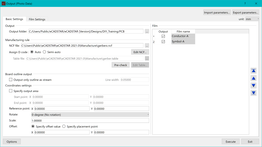
Figure 1: The Output (Photo Data) dialog
- Specify the folder into which the photo data is output.
- Set the NCF file path shown above.
- In the Assign D tool code field, select Auto.
- In the Output (Photo Data) dialog, select the Film Settings tab.
- In the Film section, click Add. The "new film1" row is added.
- Click "new film1" and change the Film name value to "Conductor-1".
- Press the Return key.
- Select Layer in the Film Settings section.
- Select Output for Conductor-1.
- Using the same procedure as above, add Symbol-A as a film.
- Select Output for Symbol-A.
- In the Basic Settings tab, Film section, confirm that the above films have been added and that Output is selected. This is shown in Figure 1, above.
- In the Output (Photo Data) dialog, click Execute.
- A message is displayed which indicates that the output of photo data has completed. Click Close to dismiss the message.
- Check that the photo data has been output as shown below, and click Close in the Information dialog.
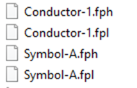
Figure 2: The Photo Data Output
- In the Output (Photo Data) dialog, click Export parameters and specify the path to save the parameter file in the Save As dialog. All of the output file names and settings are saved.
- Click Exit to close the Export (Photo Data) dialog. You have now created the Gerber files for your design. We will create the drill data in the next task.
Note
You can load the saved parameters by clicking Import parameters in the Output (Photo Data) dialog. This removes the need to specify new parameters for a similar design.
You can load the saved parameters by clicking Import parameters in the Output (Photo Data) dialog. This removes the need to specify new parameters for a similar design.
This task is demonstrated in the following video.
