
Task 23: Exporting Drill Data
In this task, you will create drill output files using the Drill Data command. This command creates the NC drill files necessary to fabricate a printed circuit board. These files are used by the manufacturer when making the board.
- Use the design from the previous task, or open Design7.pdes.
- On the Manufacture tab, click the Drill Data icon in the Manufacture output group.
- The Output (Drill Data) dialog is displayed.
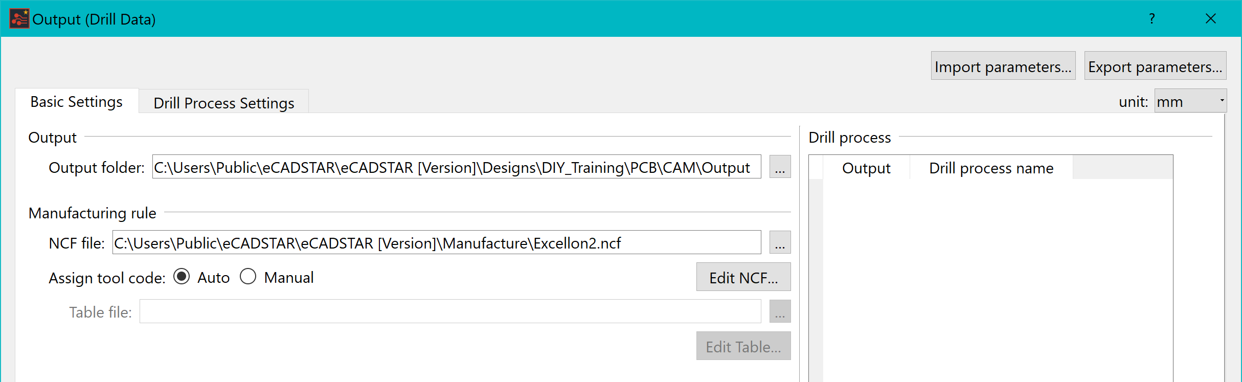
Figure 1: Output Drill Data Settings
- Specify the folder which the drill data should be exported to.
- In the NCF file box, browse to the following location and select the file Excellon2.ncf: C:\Users\Public\eCADSTAR\eCADSTAR [Version]\Manufacture.
- Set the Assign tool code field to Auto.
- On the Drill Process Settings tab, right-click and select Insert Drill Process Below on the assist menu. Alternatively, click Add. The "new step1" row is added.
- Click "new step1" and change the value in the Drill Process Name column to "Hole" and press Return.
- In the Drill Process Settings section, select Object.
- To define the holes to be exported, select the Output check box for Round hole, Slot hole, Hole in padstack (Round hole) and Hole in padstack (Slot hole). In this example, only through holes are used.
- Select Hole diameter/Hole type in the Drill Process Settings section. Output is now selected for all items.
- In the Output (Drill Data) dialog, click Execute.
- A message is displayed which indicates that the process has completed. Click Close to dismiss the message.
- The following files are produced in the output folder. Check that they are present.
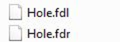
Figure 2: The Drill Output Files
This task is demonstrated in the following video.
You have now created the drill output files. We will summarize what you have learnt in the next section.
