Hole Drawing Command
The Hole Drawing command allows you to create hole drawing symbols for round holes, slot holes and holes in a padstack. A hole drawing table can also be created, and shown on the canvas.
Overview
- On the eCADSTAR PCB Editor ribbon, select Draw > Hole > Hole Drawing.
- In the Hole Drawing dialog, ensure that all required rows are selected within the Draw column.
- In the Other Settings tab, set the character width, height, spacing, pen width, character angle and justification.
- In the Shown columns table, select the relevant layers that you want to display, and click OK. A report is generated that details the size, shape and number of drills.
- Drill symbols are also generated for the active layer, on the layer specified as the generation layer. A drill table is also generated.
Task 21: Hole Drawing Creation
In this task, you will create hole drawing symbols, a hole report and a drill table that gives details of the holes in your design.
- Open the design Design6.pdes, if it is not already in use, or use your own, completed design.
- On the eCADSTAR PCB Editor ribbon, select Draw > Hole > Hole Drawing.
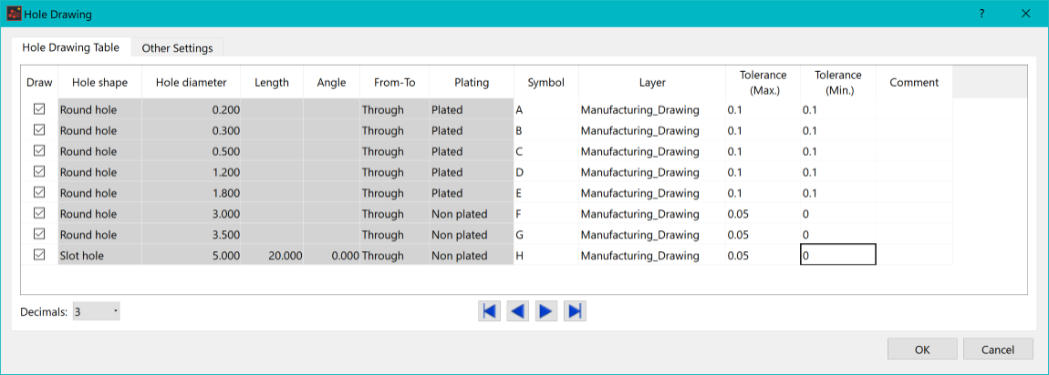
Figure 1: The Hole Drawing Settings
When the Hole Drawing dialog is launched, the Hole Drawing Table tab and the symbol positions are automatically refreshed.
- Ensure that all rows are selected in the Draw column. Specify the above settings in the dialog.
- In the Other Settings tab, specify the settings shown below.
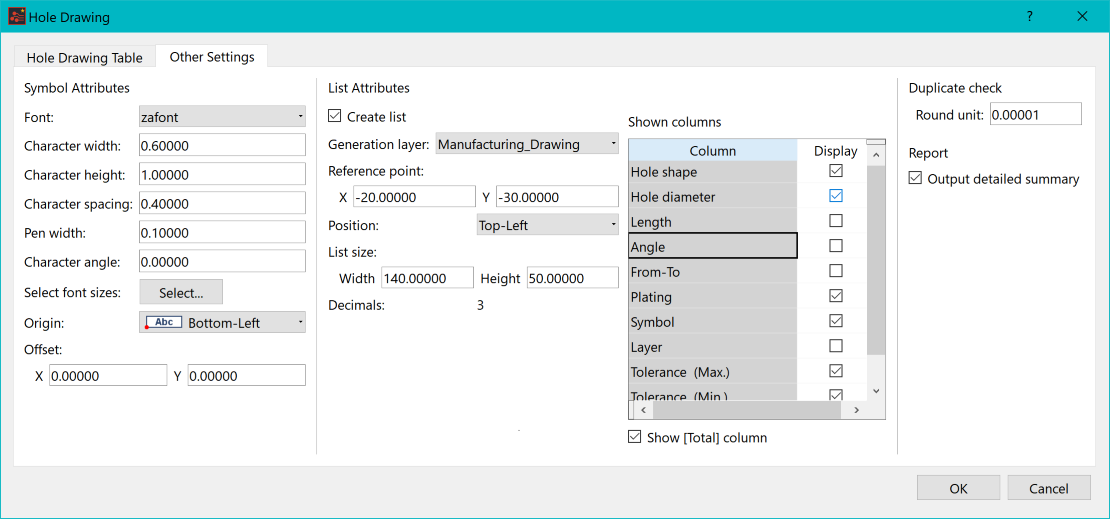
Figure 2: Setting Values from the Other Settings Tab
-
Click OK. A report is generated as shown below:
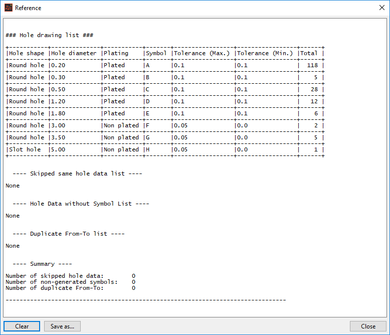
Figure 3: The Hole Drawing Report
Note that the drill symbols and drill table are also created during this process. To view these:
- Set the active layer to "Manufacturing _Drawing". The table shown below, along with the drill symbols can now be viewed within the layout area.
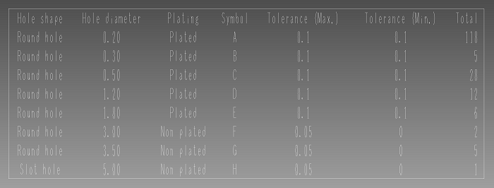
Figure 4: Hole Data Shown Within the Layout Area
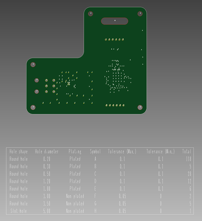
Figure 5: The Drill Drawing
This task is demonstrated in the following video.
You have now successfully created a Drill Drawing and Hole Data table.

