Task 20: Adding Dimensions
The dimensions feature of eCADSTAR allows you to add dimension lines to your design.
Overview
- On the Draw tab in eCADSTAR PCB Editor, select the required dimension type.
- Ensure that the appropriate layer is selected in the Layer Settings panel.
- Set the required values within the relevant dimension dialog.
- Click the relevant end points for the dimension. The dimension is added.
Task 20: Adding Dimensions
In this task, you will add dimensions to the board outline.
- Open the design Design6.pdes, if not already in use, or use your own, completed design.
- In the Layer Settings panel, turn on the Drawing layer columns by selecting the Show in Grid check box.
- Set the active Layer to "Manufacturing_Drawing" and ensure that the Visible drawing layer cell is selected.
- On the eCADSTAR PCB Editor ribbon, select Draw > Linear Dimension > Single.
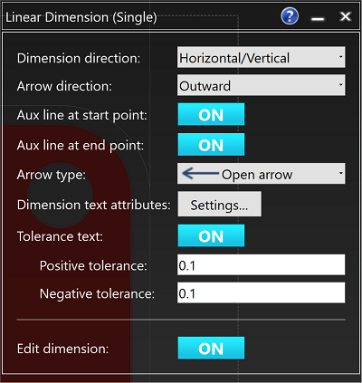
- Set the values shown below in the Linear Dimension (Single) dialog.

Figure 1: The Linear Dimension Dialog
- Toggle on the Snap
command by clicking
 on the toolbar. Alternatively,
use the shortcut key, "S".
 - Ensure that the board outline is selected as a visible layer.
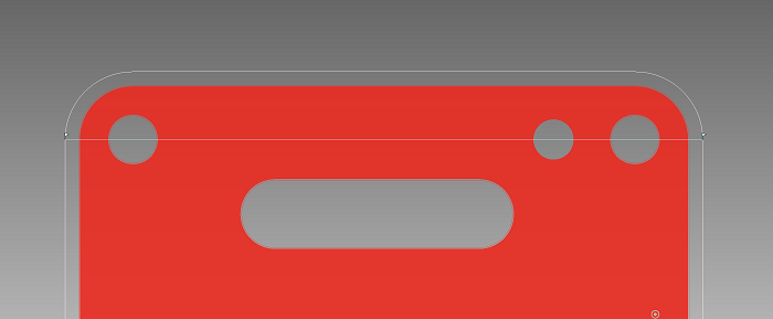
- Zoom in to the top-right corner of the board.
- Point the cursor at the left edge of the board until a flag appears, and then click the mouse.
- Move the cursor to the right edge of the board and click the mouse again. The dimension now attaches to the cursor.

Figure 2: Adding Dimensions to the PCB
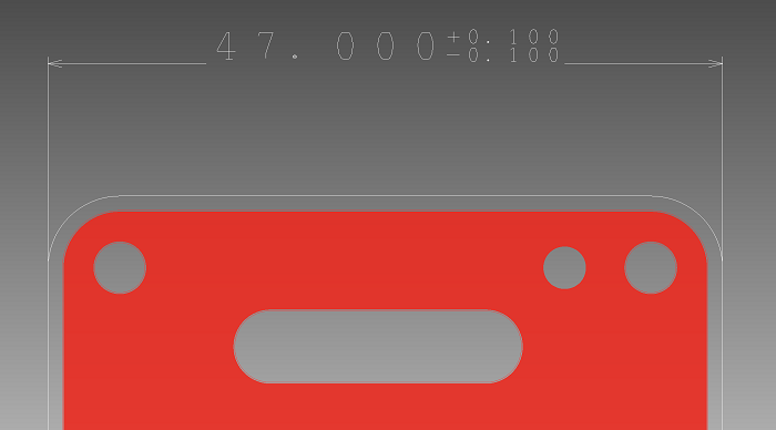
- Drag the dimension above the board outline, and click to place it as shown below.

Figure 3: Dimension added to the PCB
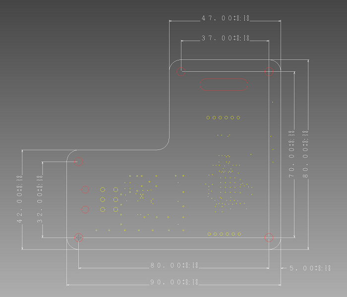
- Continue to place dimension lines until you have a design similar to the one shown below.

Figure 4: Fully Dimensioned Board
- When in any dimension mode, the positions of the dimension text and dimension lines can be modified.
- Dimensions can be placed on the grid by turning off the Snap function when placing dimensions. Press S on the keyboard to do this.
You have now added dimensions to your design. Next, you will create hole drawing symbols.

