
Task 17: Design Rule Checking
In the Design Rule Checking section, you will cover post design checking. eCADSTAR includes a full set of Design Rule Checking (DRC) tools to ensure the finished design meets all design and manufacturing rules. We will examine the available tools, and typical results below. During and after the placement and routing process, you can run the Design Rule Checking (DRC) function to perform a variety of checks on your design. The DRC function is located on the Report tab.
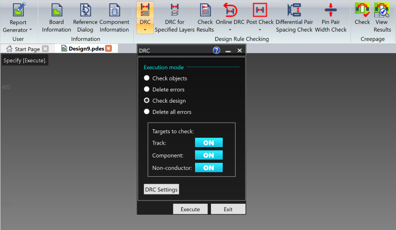
Figure 1: Running DRC
Overview
- The DRC command dialog is opened from under the Report tab.
- To check the complete design, select the Check design button and click Execute.
- Errors are displayed in the Check Results dialog.
- Clicking highlights the specific error within the work area.
- Design Rule Checking (DRC) is provided in both batch mode, and in real time.
- There are many rules to discover depending on the level to be checked.
- All design rule clearance values are defined in Design Rule Editor.
- If the clearance value defined in the design rule is violated, error marks similar to those below are displayed. The numbers displayed indicate the design rule number and in the case of the clearance violation, the minimum required clearance.
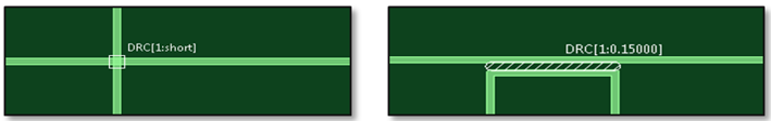
Figure 2: DRC Violations
- When Online DRC is set to ON, the design is checked in real time. However, if you temporarily set Online DRC to OFF during the design work, execute DRC to ensure there are no errors.
- The Post Check function enables errors to be displayed in real time. Set this function to ON, and as tracks are moved, DRC errors are displayed.
Task 17: Design Rule Checking
In this task you will create DRC violations to see how they are flagged using the Design Rule check functions.
- Using your design from the previous task (or load Design7.pdes), create two DRC violations: a “Cross” Short and a Clearance violation, as shown below (hint: set Conductor-1 as the Active layer, and then select Add Route on the Net/Route tab to create the shorted track. Move track command can be used to create the track to track clearance. You will need to disable the Online DRC checking process to do so). Alternatively, use a design of your own and create two errors.
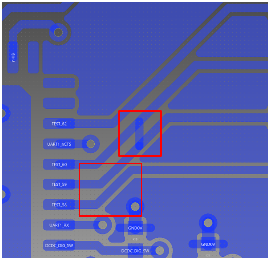
Figure 3: Short and Clearance Violations
- In the Report tab, click DRC. In the command panel, select Delete all errors and click Execute. Error marks are deleted.
- In the DRC command panel, click Exit.
- On the Reports tab, click DRC Settings from the DRC icon drop down list to display the DRC Settings dialog, as shown below.
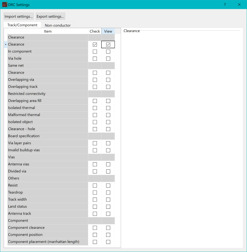
Figure 4: The DRC Dialog
- In the Track/Component tab, set the Check and View boxes as shown above. The remaining boxes should be unselected.
- Ensure that all check boxes are unselected in the Non-conductor tab.
- Close the DRC Settings dialog and select DRC.
- In the DRC dialog box, select Check design.
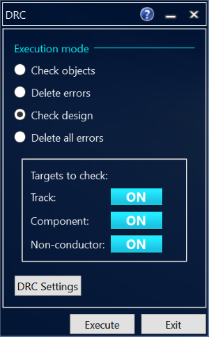
Figure 5: The DRC Dialog
- Click Execute. A list containing the errors are displayed in the Check Results dialog.
In the Check Results dialog, ensure that
 (Always
send the selected item) is toggled on.
(Always
send the selected item) is toggled on.
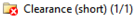
- In the Check Results
dialog, expand the Clearance folder
and confirm that an error is shown for Clearance
(short) as follows:
 .
. - Click the Clearance (short) item and error row to display the errors shown below. At the end of each check, errors are summarized in a look-up table for review, and to determine if the errors are acceptable.
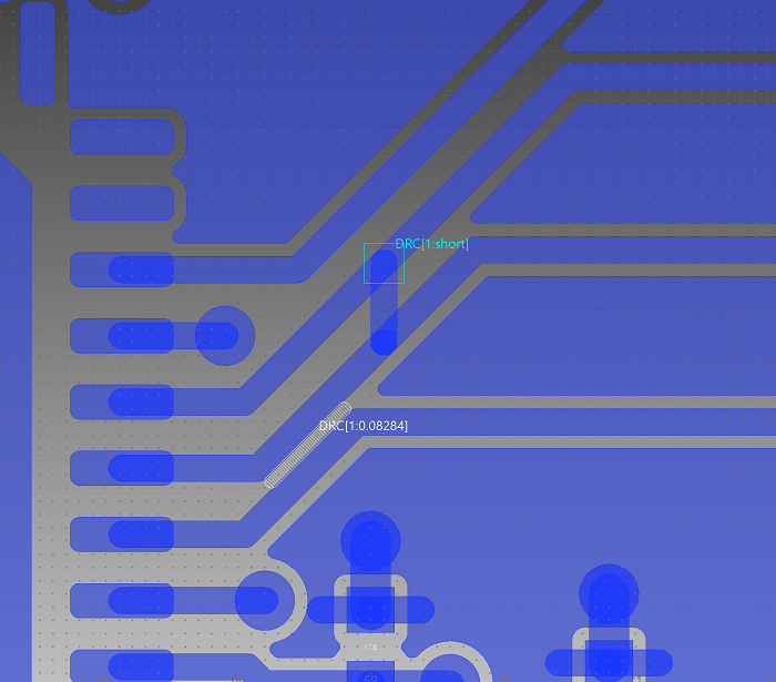
Figure 6: DRC Errors Highlighted On PCB
This task is demonstrated in the following video.
You have now learnt how to use the DRC check functions of eCADSTAR, and can confidently check your designs. You have also completed the PCB design section of this training course. You will now move on to the PCB Cosmetics section.
