Overview of Symbol Editor
In this section, you will explore Symbol Editor. This allows you to create and edit schematic symbols.

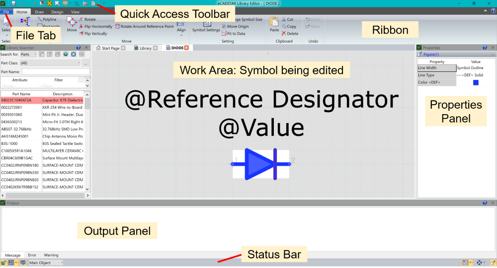
Figure 1: Symbol Editor
- File Tab: file operations and general settings are provided for the application.
- Quick Access Toolbar: access is provided to frequently-used commands, such as Undo, Redo, Display All and Zoom. You can customize the contents of the Quick Access toolbar to add tools that are available on ribbon tabs, or other tools that are unavailable by default.
- Ribbon: the ribbon is a layered element consisting of tabs, groups and controls.
- Work Area: the work area (canvas) allows you to view and edit symbol data.
- Output Panel: the Output panel returns useful messages, errors and warnings relating to the operation of the Symbol Editor.
- Properties Panel: allows you to display and edit the properties of selected items.
-
Status Bar: allows you to access commands that help with design operations, such as message logs and grids.
Note
All panels can be undocked or docked in the Symbol Editor interface.
All panels can be undocked or docked in the Symbol Editor interface.
Next topic: Creating
a Symbol
Related Topics
Drawing an Outline
Adding the Inverter Symbol
Adjusting Sheet Size and Origin
Adding Area Fills
Adding Pins
Hiding Text Fields
Adding Part Information using the Symbol Settings Dialog
Creating a Symbol for a Plated through-hole, or Surface Mount Connector
Alternate Symbols
Related Topics
Drawing an Outline
Adding the Inverter Symbol
Adjusting Sheet Size and Origin
Adding Area Fills
Adding Pins
Hiding Text Fields
Adding Part Information using the Symbol Settings Dialog
Creating a Symbol for a Plated through-hole, or Surface Mount Connector
Alternate Symbols

