
Understanding Topology Templates
Topologies are widely used in High Speed PCB design as they allow you to define the topological routing pattern for signals. They help to determine the placement of components by considering the connectivity pattern of the signal. By routing using topologies, signals can be optimized as they are routed in the same way. This ensures that signal integrity is maintained, for example across a bus.
Topologies also allow you to define branch points within the signal, as well as width change points for impedance-balanced routing. In the training design, which is routed to a DDR2 technology, the two main topologies are H-Tree and Point-to-Point. These are described below.
H-Tree topology
The H-Tree topology typically defines the routing pattern for address, command, control and clock signals that are associated with the DDR2 technology. The “H” in the name is derived from the H-shaped branch that is created by the Virtual Branch Point (VBP) splitting the two memory modules. This topology was adopted by DDR2 technologies. However, it was not the preferred method for DDR3 or DDR4 as it could not accommodate higher signalling rates.
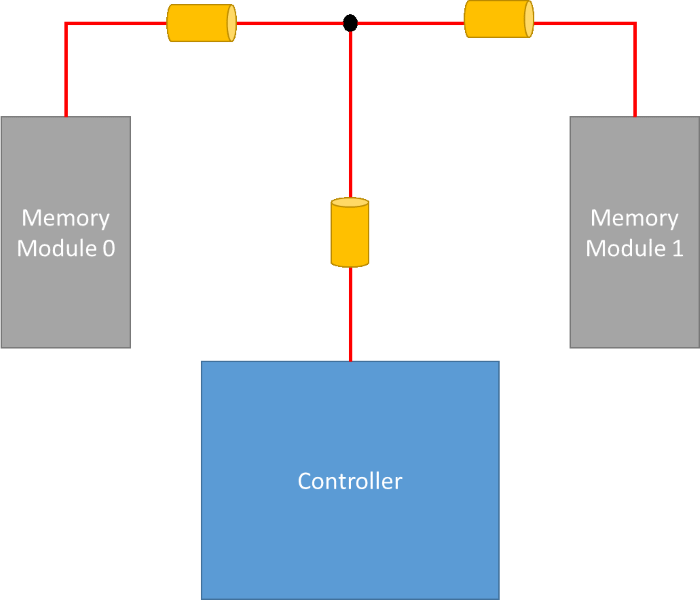
Figure 1: Basic H-Tree Topology
Point-to-Point topology
The Point-to-Point topology is the simplest form of topology used in High Speed PCB design. This topology connects two nodes using a direct transmission path. In the training design, which uses DDR2 technology, Point-to-Point topologies are used for the data lines and data strobes. In this case, more efficient signals are produced by shortening the return path for data and strobes.
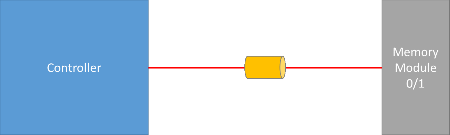
Figure 2: Point-to-Point Topology
