
Task 3: Defining the Topology Templates
In this topic, you will define the topologies that are required to route the design, whilst adhering to the DDR2 specification.
- Using the MyHSDesign1.pdes design from the previous topic, launch Constraint Browser from the Home tab on the eCADSTAR PCB Editor ribbon.
- In Constraint Browser, click Edit > Topology Template Manager on the menu, or click the Topology Template Manager button on the ribbon. The Topology Template Manager is launched.
- In the Topology Template Manager, click the Create a new topology template button shown below.
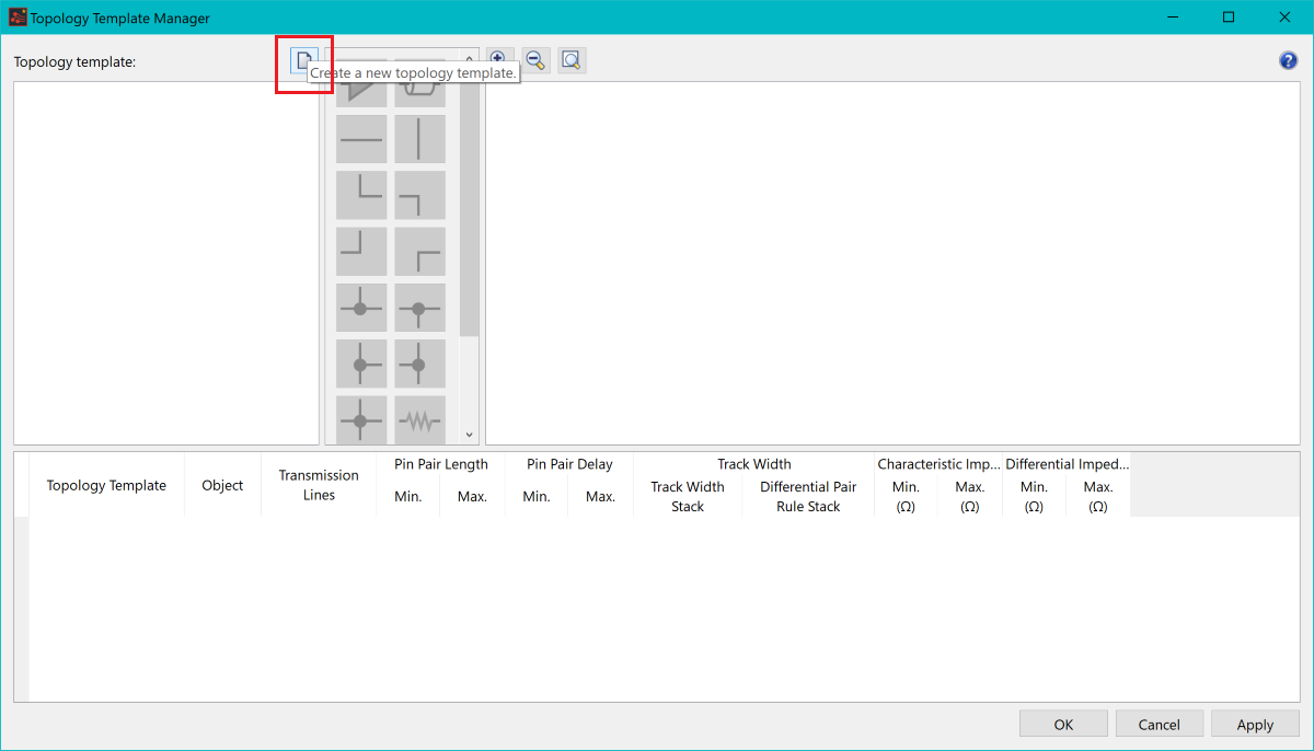
Figure 1: Topology Template Manager
The Create Topology Template dialog is displayed. This is a pre-defined topology list for creating topologies.
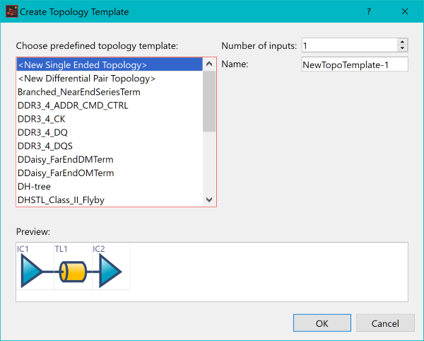
Figure 2: Create Topology Template Dialog
- From the predefined topology template list, select “DH-Tree”.
- Set the Number of inputs value to “2”, and change the Name value of the topology to “Differential_Pair_H-Tree”.
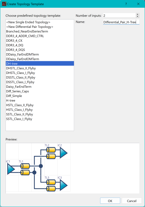
Figure 3: Create Topology Template Dialog
- Click OK to save, and close the Create Topology Template dialog.
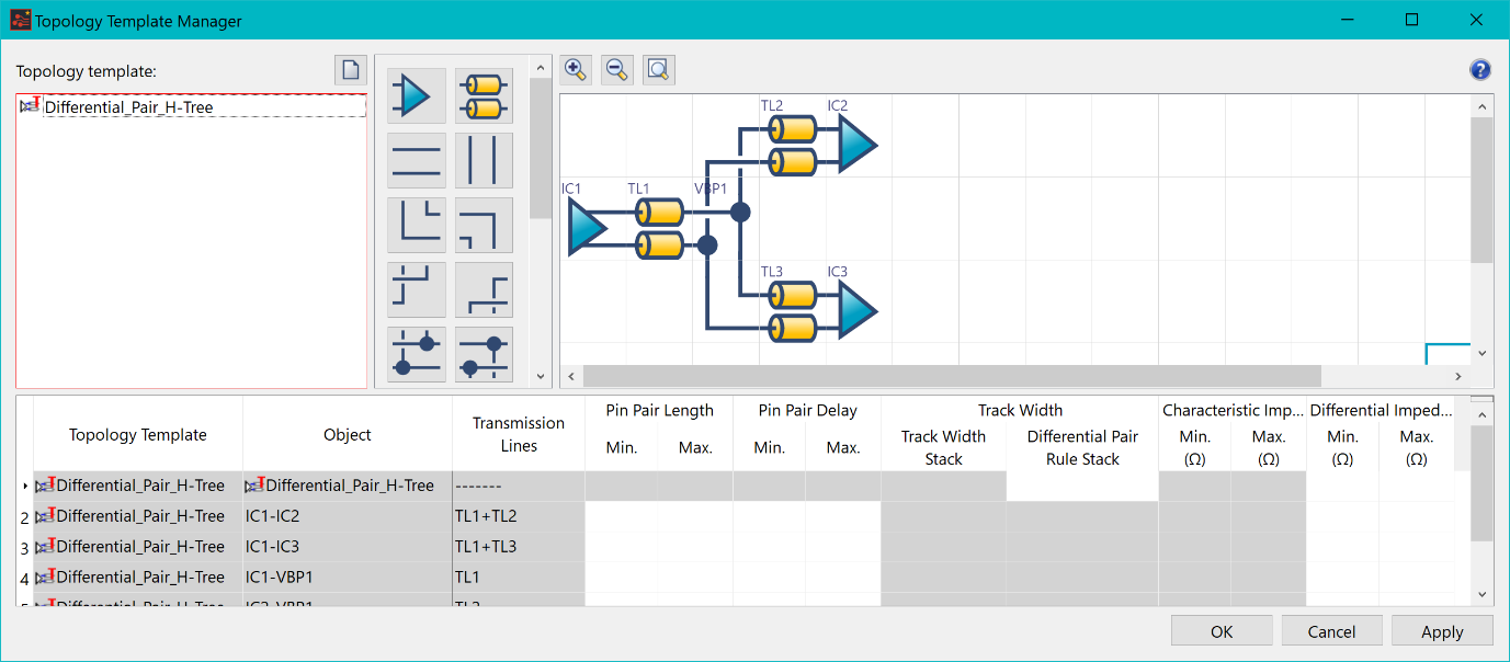
Figure 4: Topology Template Manager
- Using the same method, create a second topology template using the “H-Tree” template from the topology. Set the Number of inputs value to “2”, and change the Name value of the topology to “Single_Ended_H-Tree”.
- Click OK to create the topology.
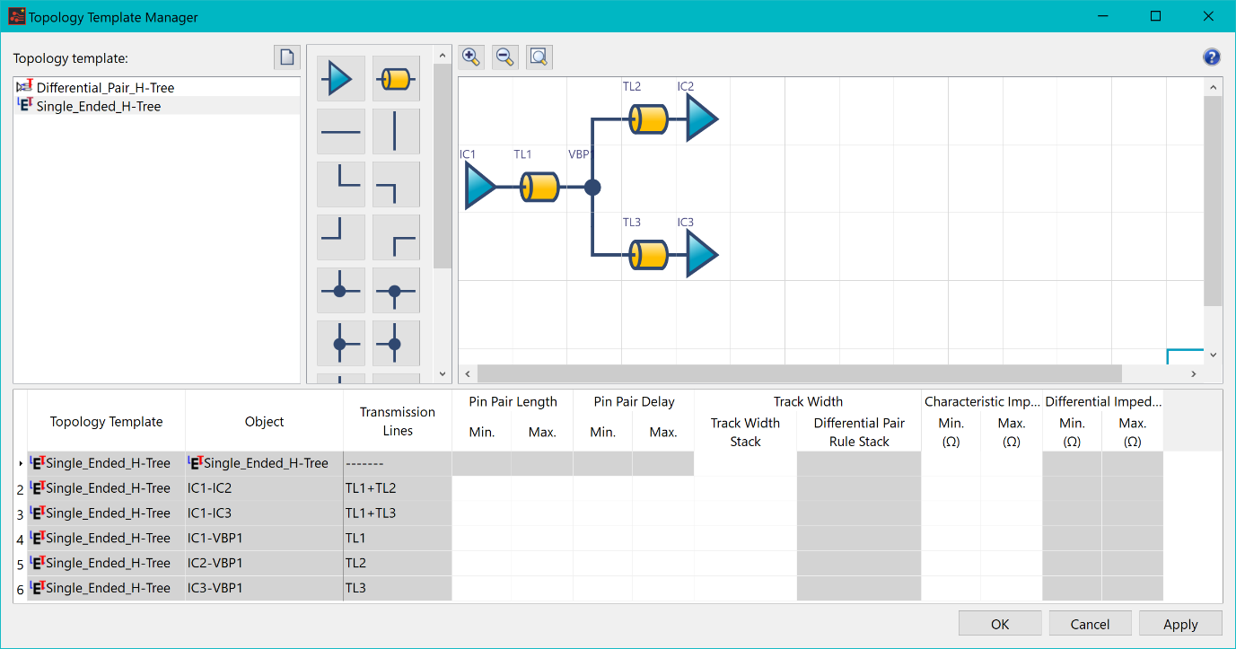
Figure 5: Topology Template Manager
- Right-click the “Single_Ended_H-Tree” topology, and select Copy. This will be used to create another single-ended H-Tree topology, but this time with termination.
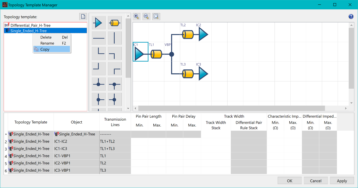
Figure 6: Topology Template Manager
- Double-click the topology, and change the name to “Single_Ended_H-Tree_Near_End_Terminator.
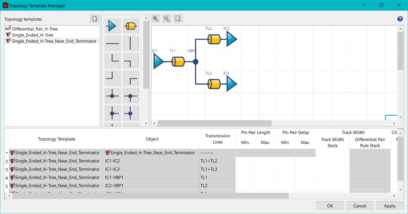
Figure 7: Topology Template Manager
- In the Topology template image, select the transmission Line "TL1".
- Right-click, and select Insert > Insert Column Right.
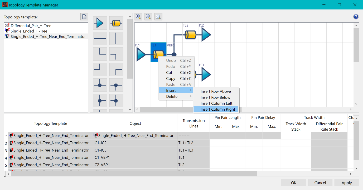
Figure 8: Topology Template Manager
- Repeat the above action two more times. Three blank columns are created between the output node and transmission line.
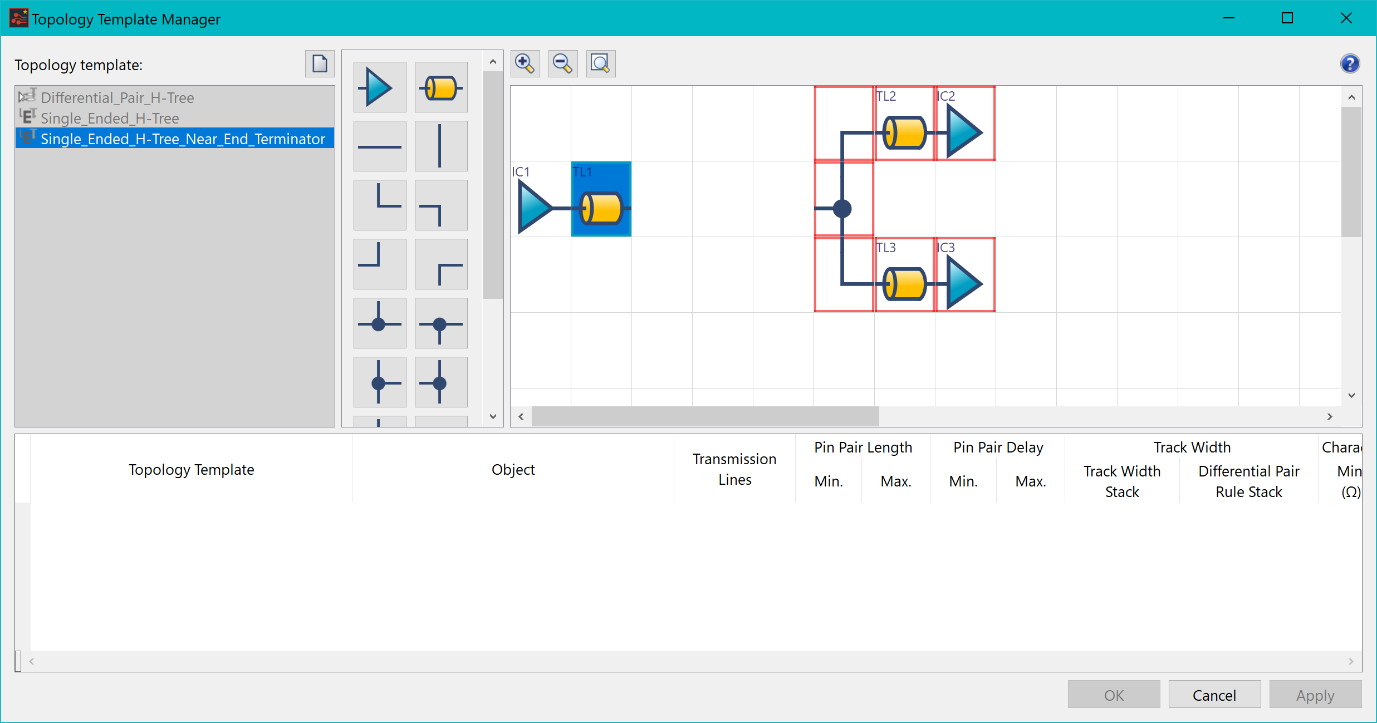
Figure 9: Topology Template Manager
- Using the toolbar, drag nodes onto the topology. Include a near-end terminator to complete the topology. The completed topology is shown below.
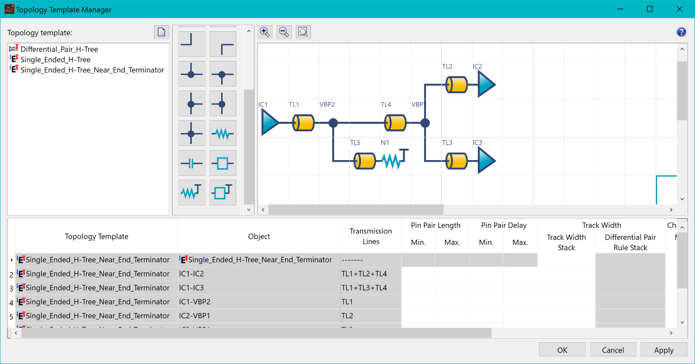
Figure 10: Topology Template Manager
- Click Apply to save the topology, A confirmation dialog will appear, Click OK and then close the Topology Template Manager.
The above procedures are demonstrated in the following video.
Related Topics
Understanding Topology Templates
