
Task 1: Creating Buses
In this topic, you will define the buses that are required for the supplied DDR2 design.
- On the Start menu, click eCADSTAR [Version] > PCB Editor [Version]. eCADSTAR PCB Editor is launched.
- In the File tab, click Open. Alternatively, click Open on the Home Ribbon. The Open dialog is displayed.
- Browse to the following location and click Open:
C:\Users\Public\eCADSTAR\eCADSTAR [Version]\Designs\DIY_Training\PCB_HS\DIY_HS_1_start.pdes.
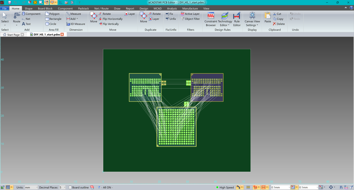
Figure 1: DIY_HS_1_start.pdes Design
- On the Home tab on the ribbon, click Design Rules > Constraint Browser. Constraint Browser is launched in a new window.
- On the Constraint Browser ribbon, click Edit > Bus Manager. The Bus manager dialog is launched in a new window.
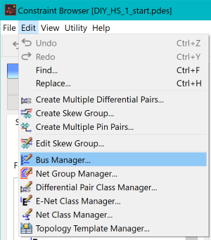
Figure 2: Constraint Browser
- In the Bus manager dialog, select the E-Nets LPDDR2_CA[0] to LPDDR2_CA[9] from the available signal list.
- In the Create Bus box, name the bus "LPDDR2_CA[0-9]".
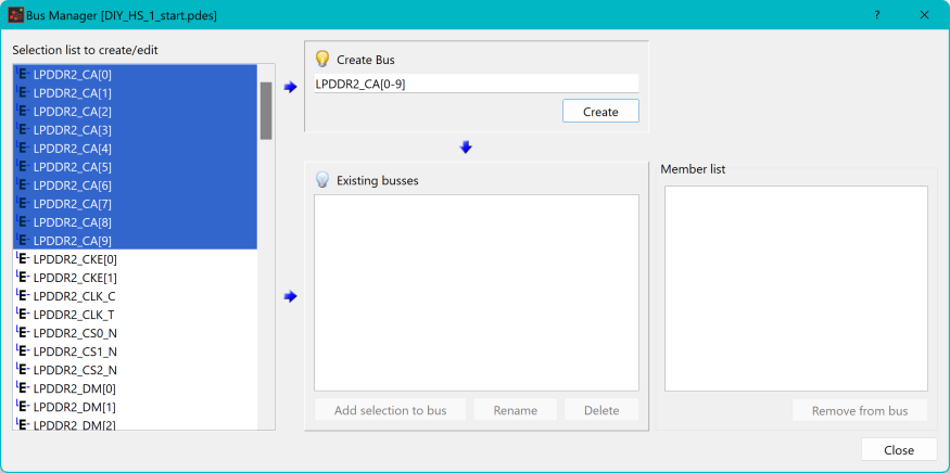
Figure 3: Bus Manager Dialog
- Click Create to create the bus.
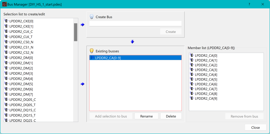
Figure 4: Bus Manager Dialog
- This is shown in the Signal tree with the "bus" icon.
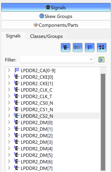
Figure 5: Signal Tree
- Using the same method, create the following additional buses.
| Bus Name | Signals |
|---|---|
| LPDDR2_CKE[0-1] | LPDDR2_CKE[0-1] |
| LPDDR2_DQ[0-63] | LPDDR2_DQ [0-63] |
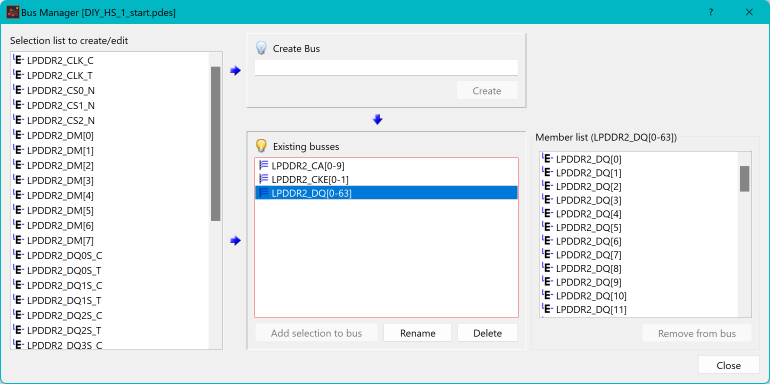
Figure 6: Bus Manager Dialog
- Save the design to the location: C:\Users\Public\eCADSTAR\eCADSTAR [version]\Designs\DIY_Training\PCB_HS\MyHSDesign1.pdes. You will use this design later in the course.
This above procedure is demonstrated in the following video.
