
Task 5: Assigning Topology Templates
In this topic, you will assign the topology template to the relevant E-Nets and Differential Pairs.
- Using the MyHSDesign1.pdes design from the previous topic, ensure that the View box in Constraint Browser is set to E-Net.
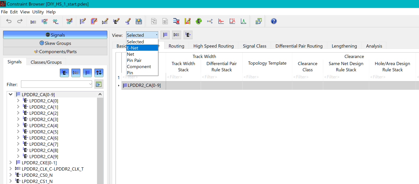
Figure 1: Constraint Browser
- In the Signals tab in Constraint Browser, select the bus "LPDDR2_CA[0-9]".
- Select the Design Rule tab as shown below, and select all signals in the Topology Template column.
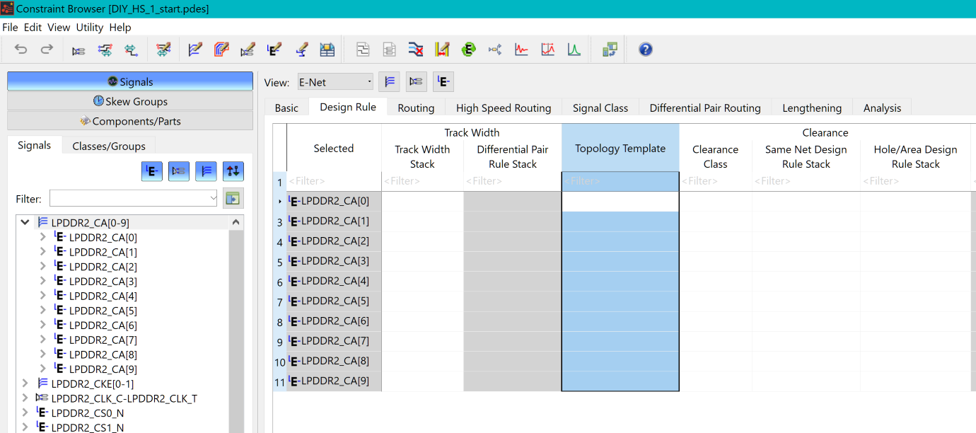
Figure 2: Constraint Browser
- Point the cursor in the Topology
template cell shown below, and click the displayed
 button. The Assign Topology
Template dialog is displayed.
button. The Assign Topology
Template dialog is displayed.

Figure 3: Constraint Browser
- In the Assign Topology Template dialog, ensure that all signals are selected that are associated with the LPDDR2_CA[0-9] bus.
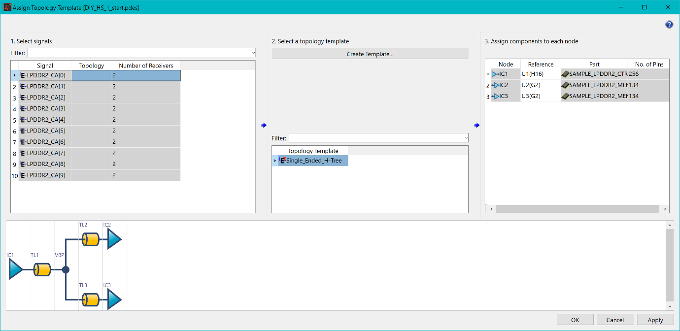
Figure 4: Assign Topology Template Dialog
- Ensure that the Single_Ended_H-Tree topology template is selected.
- Ensure that the contents of the Assign components to each node section matches the above image.
- Click Apply to assign the topology to the selected signals.
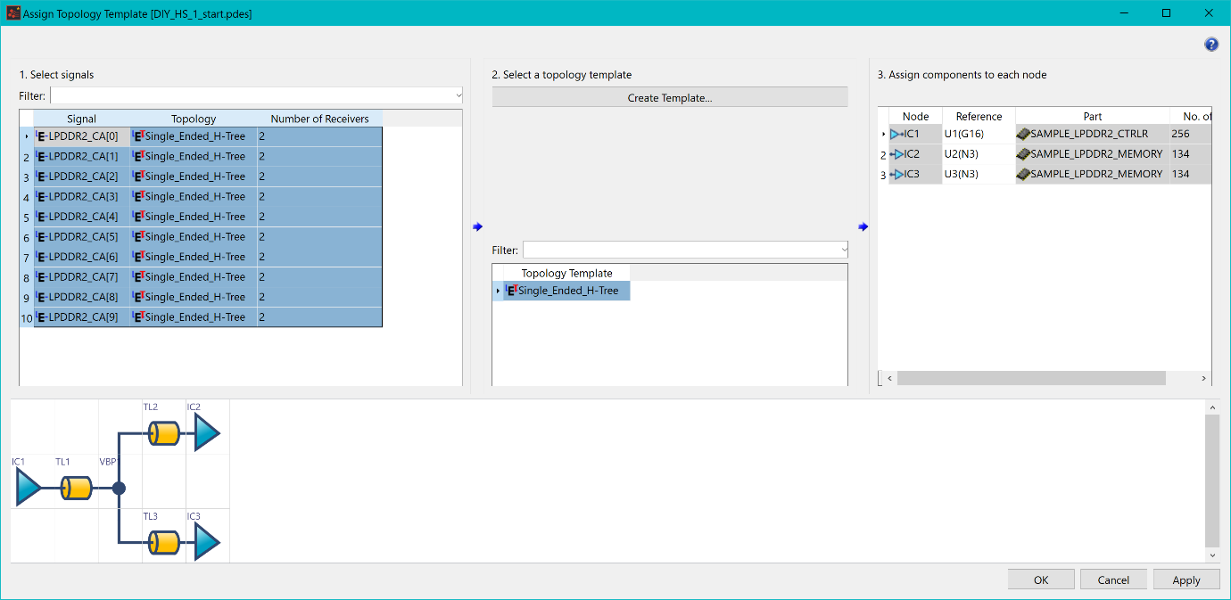
Figure 5: Assign Topology Template Dialog
- Following the same procedure as described above, assign the following topologies to the nets.
| Signals | Topology |
|---|---|
| LPDDR2_CKE [0-1] (E-Nets) | Single_Ended_H-Tree_Near_End_Terminator |
| LPDDR2_CLK_C-LPDDR2_CLK_T (Differential Pair) | Differential Pair_H-Tree |
- When all topologies are assigned, save the design. Virtual branch points should now be visible on the canvas, and can be interacted with.
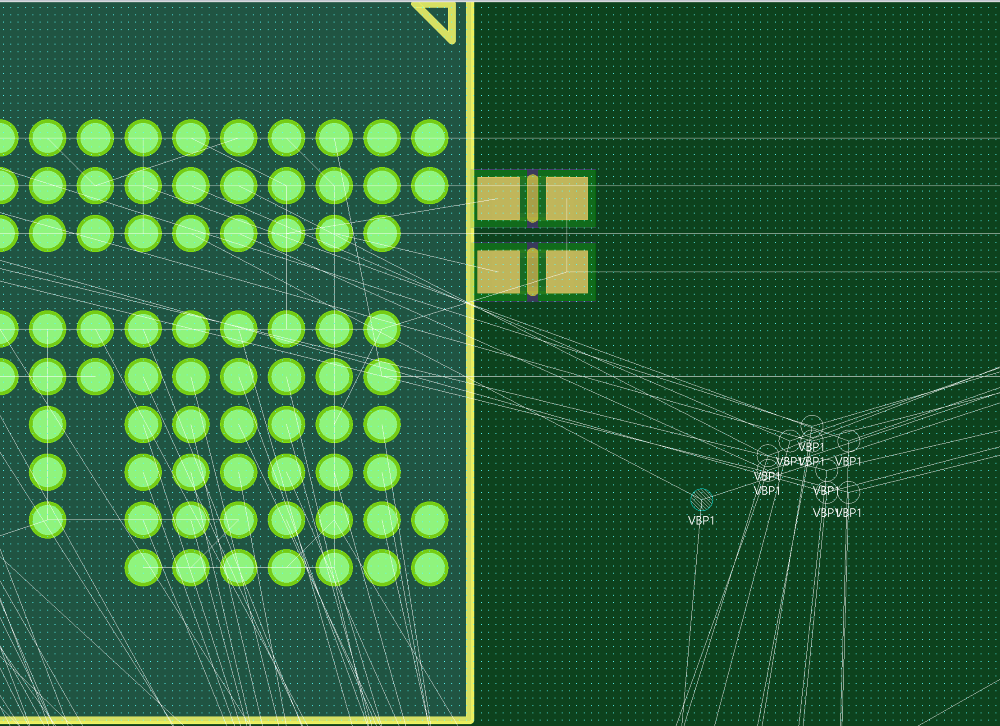
Figure 6: Virtual Branch Points
The above procedures are demonstrated in the following video.
