
The Move command allows you to move an object to a new position on the canvas, using the settings specified in the Move dialog. You can also move objects on the canvas by dragging and dropping them at the required location. The Move dialog is not displayed when dragging objects. Execute this command by selecting Home > Move > Move on the eCADSTAR PCB Editor dialog.
The Move command is available in 2D View mode and 3D View mode, although only components can be moved in 3D View mode. After executing the Move command, you can move a component by single grid position using the Shift key and the relevant arrow key. See: Moving a Component by Single Grid Positions.
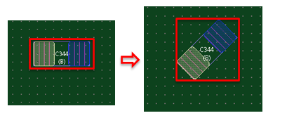
You can also move components as follows.
- On the canvas, select them, and use the Shift key and the relevant arrow key. See: Moving a Component by Single Grid Positions.
- Specify their new position in the Properties Panel, Coordinates box.
- Multiple objects can be selected using the Ctrl key.
- If you by press the R key when this command is invoked, then the command is closed and the Rotate command is launched. This allows you to rotate a selected object on the canvas.
- If you press the E key when this command is invoked, then the selected item is rotated by the value specified in the Rotation step box.
- The Move and Duplicate (Move) commands have several fields in common. If you update a setting that exists in both command dialogs, then both command dialogs are updated.
After selecting an object, right-click to access the assist menu. This allows you to execute a range of commands to configure the duplicated object. For example, you can rotate or mirror the object, or specify the placement side of the board. See: eCADSTAR PCB Editor Assist Menu.
Command dialog
Drag reference point
Allows you to select the drag reference point when you move an object on the canvas. This setting is ignored if you select ON in the By origin field.
| Value | Description |
|---|---|
| Vertex | When you move an object on the canvas, the drag reference point is defined as the nearest vertex to the position that you click on the object. |
| Point | When you move an object on the canvas, define the drag reference point by clicking a position on the object. |
| Center | When you move an object on the canvas, the drag reference point is defined as the center of the object. |
Rotation step
This field allows you to set the rotation angle that is applied when Rotate by Specified Angle is selected on the assist menu.
| Value | Description |
|---|---|
| Real number greater than -360, and smaller than 360. | Specify the rotation angle applied when Rotate
by Specified Angle is selected from the assist menu. The
value that you specify is displayed in the command dialog when
you next execute the following commands in eCADSTAR PCB Editor:
Move Rotate Paste Duplicate (Move) Duplicate(Rotate) Align Component Rotate Around Reference Point Rotate by Specified Angle Note If you press the E key when this command is invoked, then the selected item is rotated by the value that you specify. |
Conductor
This section allows you to specify whether net information is kept when an object is moved. It also allows you specify that tracks that are connected to a component are rerouted when you move the component.
Keep net
| Value | Description |
|---|---|
| ON | If selected, then all net information is kept when the object is moved. If a trunk is selected, then this setting is not applied. |
| OFF | If selected, no net information is kept when the object is moved. |
Reroute
| Value | Description |
|---|---|
| ON | If selected, then the tracks that are connected to the component
are rerouted in 45-degree increments when you move the component.
This process
ignores Online
DRC
constraints, and therefore does not avoid obstacles. DRC errors
may be created as a result. It is recommended that Post
Check is toggled on to highlight any errors on the canvas
that are caused by moving a component. This is done by selecting
Report > Design Rule Checking
> Post Check
on the eCADSTAR PCB Editor
Ribbon. Note If there are thermal lines on the component, then they are not rerouted and are left in the same position. |
| OFF | If selected, then the component is moved without rerouting the tracks that are connected to it. |
Component
When moving components, this section allows you to select whether other components are pushed away. You can also select whether the footprint origin is used during the move process, rather than snapping to a vertex within the footprint. You can also select whether components are moved that are in the same placement group as the object that is moved.
Pushing
Allows you to specify whether components are pushed away to maintain clearance when a component is moved. The pushed components are moved only in the X and Y directions, rather than diagonally. They are placed at the closest error-free location.
When moving a component, a rectangle is created around the boundaries of the component. This is used to push the other components. Consequently, the push boundary is larger if a component to be moved is at an angle other than orthogonal. For example, If a component is rotated by 45 degrees, then the size of the push boundary is almost doubled.
| Value | Description |
|---|---|
| ON | Other components are pushed away to maintain clearance with the moved component. The clearance between components is set in the Component area - Component area box in the Rule Editor Dialog: Placement tab. The Exclude specified pin count or more box is made available. |
| OFF | Other components are not pushed away when moving a component. |
Exclude specified pin count or more
| Value | Description |
|---|---|
| Integers greater than or equal to 0 | A component is not pushed away whose number of pins exceeds the specified value. This box is made available when Pushing is set to ON. |
By origin
Allows you to specify whether the footprint origin is used during the move process, rather than snapping to a vertex within the footprint. If you select ON in this field, the Drag reference point setting is ignored.
| Value | Description |
|---|---|
| ON | When moving components, the footprint origin is used during the move process, and the Drag reference point setting is ignored. |
| OFF | When moving components, any vertex within the footprint can be snapped to during the move process. |
Move entire placement group
| Value | Description |
|---|---|
| ON | If selected, components are also moved that are in the same placement group as the object that is moved. |
| OFF | Only the selected components are moved when a component is moved. |
