
Task 13: Configuring the Grids Tab
The Grids Tab contains grid settings for tracks, vias, placement and for non conductor objects.
-
Click the Grids tab as shown below.

Figure 1: Grid Settings
- In the Grid name box, enter a value of "0.1mm" and click Add.
- In the X column, specify a value of "0.10000".
- In the Y column, specify a value of "0.10000".
- Repeat the above operations for the 0.125mm, 0.2mm, 0.25mm, 0.4mm and 0.5mm grids, filling out the X and Y pitches as "0.12500", "0.20000", "0.25000", "0.40000" and "0.50000" respectively.
Set the default grids as follows:
- In the Track grid box, select 0.1mm.
- In the Via grid box, select 0.1mm
- In the Placement grid box, select 0.125mm.
- In the Non-conductor grid box, select 0.1mm.
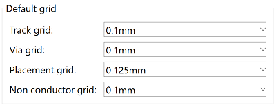
Figure 2: Default Grid Dialog
- Click Save.
This task is demonstrated in the following video.
