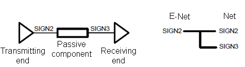
An E-Net includes all relevant signals, from the transmitting end (driver) to the receiving end (receiver), and can contain multiple nets. The following image shows an E-Net that contains a single net.

The following image shows an E-Net that contains a passive component and two nets. Resistors, capacitors, diodes, inductors and filters are passive components.
The set of pins associated with the logical signals between components is called a series. An E-Net is the net which contains the general signals in a series. The combination of pins in a series is determined by the reference name, attributes, and the device type and passive type of the components.
Attributes of a Series
The attributes that define a set of pins as a series are described below.
| Class | Attribute Name | Description |
|---|---|---|
| Component Part | Device Type | If the following values are set, then the component pins are
recognized as part of a series.
|
| Component Part | Passive Type | This attribute specifies the component type.
|
| Component pin Part pin Pin assignment pin | Passive Connectivity |
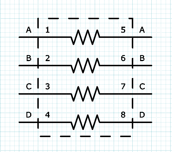
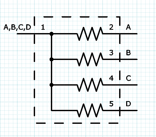
This attribute specifies the pin types that are recognized as a passive connection. Array resistor: if the Passive Connectivity attribute is set for the pins, then each of the pin sets 1-5, 2-6, 3-7, and 4-8 is recognized as a series. This is illustrated below.
Differential filter: pin set 1-2-3-4 is recognized as a series. This is illustrated below.
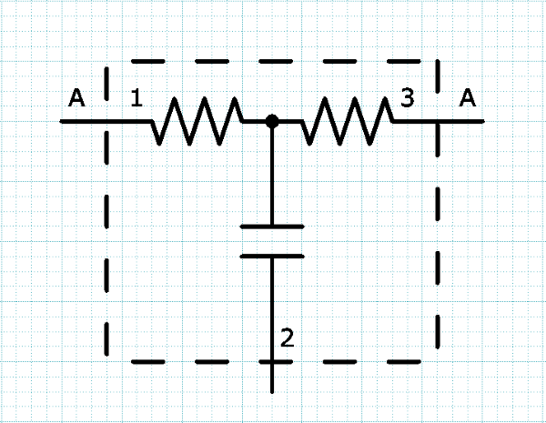
3-pin filter: pin set 1-3 is recognized as a series. A power net or ground net is connected to pin 2. This is illustrated below.
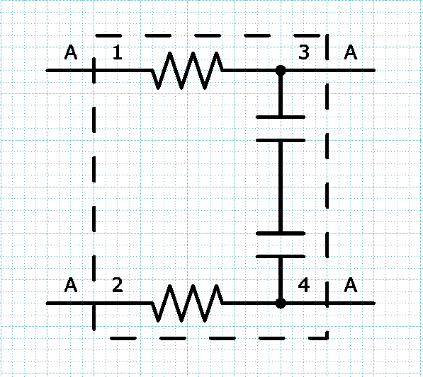
Array component with a common pin: multiple text strings must be specified in the attribute Passive Connectivity. This is illustrated below.
|
Rules for Defining Pins as a Series
The rules for defining pins as a series have a component level and a pin level. Sets of pins are defined as a series if they satisfy both conditions. These levels are described below.
Component Level
Sets of pins are defined as a series if they satisfy the following conditions.
- The value of the Device Type attribute is Passive.
- The value of the Passive Type attribute is set to Capacitor, Resistor, Inductor, Diode or Other Passive. Alternatively, the reference designator begins with one of the following component prefixes and is followed by only numbers: Resistors, Inductors, Diodes or Capacitors. These values are shown in the E-Net Prefix Definition dialog, and are specified in the E-Net Prefix Definition Dialog in eCADSTAR Library Editor. To view the component prefixes in eCADSTAR Schematic Editor, click Utility > E-Net Prefix Definition in Constraint Browser.
- Values for Passive Connectivity are set to pair internal passive connectivity.
Pin Level
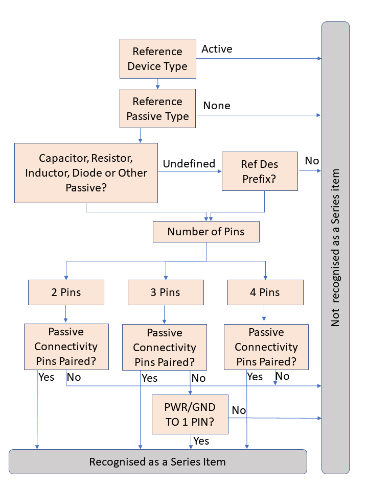
The following diagram shows the process used to define a set of pins as a series.