
The Add Net dialog allows you to add nets to a schematic sheet. You can define labels for the nets, and specify that they are automatically incremented when multiple nets are added. It is displayed by clicking Home > Add > Net on the eCADSTAR Schematic Editor ribbon.
Dialog
| Value | Description | |
|---|---|---|
| Net Label | Allows you to define the label that is associated with a net.
The value that you specify is shown in the Net
Label box, in the Properties Panel. For the Add Net, Net/Bus and Increment Net commands and in the Properties Panel, if you attempt to change a label to one that already exists, then a confirmation dialog is immediately displayed. This asks whether to merge the nets.
The dialog is shown if duplicate net labels exist for the following objects.
Duplicate net labels may be detected on all sheets in the circuit, including instance hierarchy. However, consider the following for global connectors.
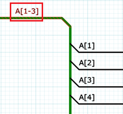
Note If the bus name “X[1-4]” exists, and Use array syntax is selected in the Assignments dialog, then:
For a connected net, if you specify a label when one is not already assigned, then the net names that are listed in the Net/Bus command, Suggested labels box, are excluded from this check. They are also excluded if the specified label is contained within the existing name. For example, if you specify a label for the highlighted bus below, then:
For an unconnected net, specified net names are not excluded from this check. |
|

|
Displays the Select Net Label dialog. This allows you to select a net label from those that already exist in the design, or if the connection has already been started, based on the start node. | |
| Auto Label | ||
| None | The net label that you specify in the Net Label box is used for all the nets that you add. | |
| Increment | For net labels that contain a numerical suffix, this setting
allows you to automatically increment the suffix when you add
multiple nets. If a net label contains a numerical suffix, then it is automatically incremented when you add multiple nets. For example, if you specify a net label of A100, then subsequent nets that you add are assigned net labels in the following sequence: A101, A102, A103. Net labels are also incremented if they contain numerical suffixes that are within square brackets |
|
| Bus/Pin | The net label is set automatically from the bus (next unused name in bit order) or pin (pin label), based on the following priority:
When this is selected, the Net label field is disabled. Note When Port Net Label is ON and the net connects to a named connector ( Global/Sheet/Hierarchy Connector, Power and Ground), the net label is set by the Port Net Label. |
|
| Wiring Mode | Select the input mode for nodes. If Auto wiring or Semi-auto Wiring is selected, pins that are in the way of the net being routed are automatically avoided. | |
|
Auto Wiring |
Allows you to specify only the start and end points. Intermediate nodes are generated automatically. Note
|
|
|
Semi-auto Wiring |
Specify intermediate nodes after specifying the start and end points. |
|
|
Manual Wiring |
Specify nodes sequentially from the start point. |
|
| Angle Lock | If Manual Wiring is selected in the Wiring Mode box, then you can specify that nets can only be placed on the canvas in increments of 45 degrees or 90 degrees, or can be placed at any angle. | |
|
|
Free | Nets can be placed on the canvas at any angle. |
| 45-degree | Nets can only be placed on the canvas in increments of 45 degrees. | |
| 90-degree | Nets can only be placed on the canvas in increments of 90 degrees. | |
| Through Connection | Allows you to connect objects when placing a net on a schematic
sheet; see Through
Connection.
Note If Auto Wiring is selected in the Wiring Mode field, then Through Connection is automatically set to OFF. |
|
| ON | Objects on the placed net are connected. If selected, then Manual wiring is automatically selected in the Wiring Mode box. | |
| OFF | Objects on the placed net are not connected. | |
| Ripper Direction | Selects the direction in which the ripper is dragged. | |
| Clockwise | Tilt the ripper direction clockwise, against the direction in which the T-shape section of the bus, or the net connected to the bus, is added. | |
| Counterclockwise | Tilt the ripper direction counterclockwise, against the direction in which the T-shape point of the bus, or the net connected to the bus, is added. | |
| Specify Color | Allows you to specify the color of the net. | |
| ON | If selected, the Color box is made available. | |
| OFF | If selected, the Color box is made unavailable. | |
| Color box | Click the Color box to select a color in the Select color dialog. | |
| Line Width | Select the line width of the net by selecting it in the Line Width box, or select <DEF>
to specify that the default value is used.
|
|
| Terminate with Symbol | Allows users to terminate the net with either a Power, Ground, Sheet or Global Connector. | |
| ON | If selected, the net is terminated on a Symbol. This is executed by either double clicking the left mouse button or clicking the right mouse button and selecting finish. This enable the Symbol and Rotation step fields in the dialog. | |
| OFF | If selected, the net will not terminate with a symbol. This disables the Symbol and Rotation step controls. | |
| Symbol | Enabled when Terminate with Symbol is ON. Lists all the power, ground, sheet, and global connectors, that are available in the eCADSTAR Library Editor to terminate the net on. | |
| Rotation step | Enabled when Terminate with Symbol is ON. Specify the angle of rotation for the specified symbol (real number greater than -360 but smaller than 360). |
Assist Menu
