
In High Speed and non High Speed environments, the Routing Balloon displays pin pair data when routing and configuring tracks on the canvas. In a High Speed environment, constraints data is shown for pin pairs that are assigned to either E-Nets or Skew Groups. The extent to which specified constraints are met is represented visually in the Routing Balloon. Toggle on this dialog by clicking View > Canvas > Routing Balloon on the eCADSTAR PCB Editor ribbon.
- When displaying the Routing Balloon:
- if you toggle it on for a design, then it is displayed for all open designs.
- if you toggle it off for a design and switch to a design in which it is displayed, then it is also displayed in the original design.
- When routing a track with Activ-45 selected in the Add Route dialog, Routing style box, data for the relevant pin pair is not updated in real-time in the Routing Balloon.
Non High Speed Environment
When routing a track using the Add Route command in a non High Speed environment, the net associated with the track and the length of the track, from the originating pin, is displayed. This illustrated below.
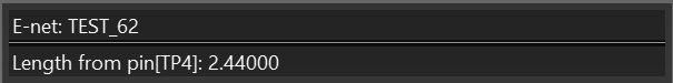
When lengthening a track using the Lengthen command, the net associated with the track is displayed.
High Speed Environment
In a High Speed environment, the Routing Balloon displays data for pin pair constraints that are assigned in Constraint Browser to either E-Nets or a Skew Group. This allows you to meet constraints when routing or lengthening tracks.
E-Nets
When routing or lengthening E-Nets, the current length of the pin pair is displayed, as well as the estimated manhattan length of the remaining unrouted track. The distance from the pin that the track is routed from is shown. The length constraints that are specified for the E-Net are shown. These are also represented visually by the two white triangles. The relevant constraints are met when the colored bar is within these triangles. In the following image, the red bar indicates that the constraints have not been met. In the following example, the minimum and maximum constraints for the pin pair length are set to 120 and 150, respectively.
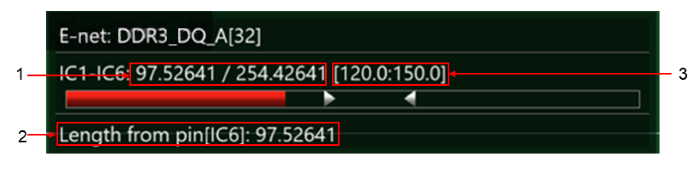
1: Current length of the pin pair / estimated manhattan length of the remaining unrouted track.
2: Distance from the pin that the track is routed from.
3: Range of constraints for the E-Net, in the following format: minimum constraint:maximum constraint.
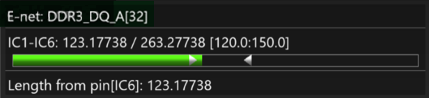
In the following image, the relevant constraints have been met. This is indicated by the colored bar being within the white triangles, and being colored green.
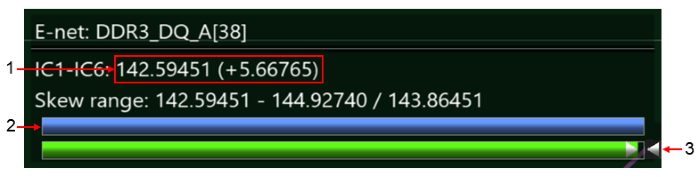
Skew Groups
When routing or lengthening E-Nets, the Routing Balloon displays skew constraints that are specified for Skew Groups. Length differences compared to the base signal are also displayed. If a base signal is not defined, then length differences compared to the longest pin pair length within the Skew Group are displayed. Colored bars are displayed which indicate the extent to which the track is routed, and whether the skew constraints are met for the net. If the skew constraints are met, then the lower bar is colored green, and its end is positioned between the white triangles.
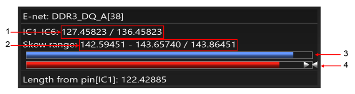
1: Current length of the pin pair / estimated manhattan length of the remaining unrouted track. This value is updated as you route the track.
2: The skew range and the base value are displayed in the following format: minimum skew - maximum skew / base value. If a base signal is not defined, then the base value refers to the reference signal.
3: Indicates the extent to which the track is routed. The partially displayed blue bar indicates that the track is not completely routed.
4: Indicates whether the skew constraints are met for the E-Net. As the lower bar is colored red and its end is not displayed between the white triangles, this indicates that the skew constraints are not met.
If the Lengthen command is used to adjust the length of the track, in order to meet constraints, then the following information is displayed in the Routing Balloon. This image shows the fully-routed E-Net which meets the skew constraints.
1: The pin pair length at its current point. Before you accept the lengthening value, the value that is added by the Lengthen command is displayed in brackets.
2: The fully displayed blue bar indicates that the track is completely routed.
3: As the lower bar is colored green and its end is displayed between the white triangles, this indicates that the skew constraints are met.
