
The Padstack command allows you to add padstacks or reinforcing vias to the board (only available in 2D View mode). It is executed by selecting Padstack > Pad/Padstack > Padstack on the eCADSTAR PCB Editor ribbon. The Padstack dialog is displayed.
Input Mode
Allows you to specify whether padstacks or reinforcing vias are added to the board, by selecting Padstack or Reinforcing via respectively. Specify the following settings for the relevant input mode.
Padstack
Select Padstack to add a padstack to the board. Specify the settings in the Padstack dialog.
| Value | Description | |
|---|---|---|
| Rule Library vias | Allows you to restrict the number of padstacks that can be selected in the Padstack name box by specifying that they must be listed in the Available padstacks box in the Rule Editor dialog, Vias tab. | |
| ON | Padstacks can only be selected in the Padstack name box if they are displayed in the Available padstacks box in the Rule Editor dialog, Vias tab. | |
| OFF | Any padstack in the library can be selected in the Padstack name box. | |
| Padstack name | Allows you to select the default padstack, or specify a padstack by selecting it from this box. The padstacks that are listed are specified in the Available padstacks box, in the in the Rule Editor Dialog: Vias Tab. | |
| Default Padstack | The padstack to be added is automatically determined by the rule area and Via specification of the design rules. | |
| [Padstack name] | The padstack with the specified name is added. | |
| From-To | Specify the "From" layer and "To" layer for the padstack to be added. | |
| Angle | Set the angle of the padstack to be added (real number greater than -360 but smaller than 360). | |
| Push aside | Allows you to specify whether tracks that become obstacles are pushed away when an object is added or edited. Specify how tracks are pushed away using the Push aside mode box. | |
| ON | When an object is added or edited, routing tracks that become obstacles are pushed away | |
| OFF | If selected, nothing is pushed away. The Push aside mode field is made unavailable. | |
| Push aside mode | Allows you to set whether bends in segments are generated when obstacles are pushed away. This field is made unavailable if Push aside is set to OFF. | |
| Tidy | Obstacles are pushed away by generating bends in segments. | |
| No tidy | Obstacles are pushed away without generating bends in segments. |
Reinforcing via
Select Reinforcing via to add reinforcing vias between area fills on different layers that have the same net. By connecting specified layers together, reinforcing vias provide structural reinforcement for the board, and improve electrical performance. They are typically associated with power and ground layers. If Reinforcing via is selected, then specify the relevant settings in the Padstack dialog, and select two area fills on the canvas. Left-click the first area fill, and then press the CTRL key and click the second area fill. The reinforcing vias are immediately previewed on the canvas, and a message is displayed which shows the total number that will be added when you click Execute.
| Value | Description | ||
|---|---|---|---|
| Location to generate vias | For the overlapping area between two specified area fills, this section allows you to specify the position of the generated vias. | ||
| Inside only | Reinforcing vias are generated only on the inside of the overlapping
area between the specified area fills. If selected, then the Parameters for inside section is made
available. This section allows you to specify either a Grid or Staggered
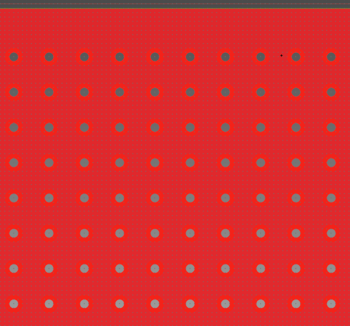
Grid pattern for the reinforcing vias. The following image
shows reinforcing vias that are generated on the inside of an
area fill using the Grid pattern.
|
||
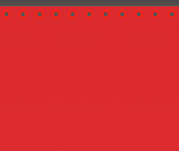
| Outline only | Reinforcing vias are generated only along the outline of the
overlapping area between the specified area fills. This is illustrated
below.
|
||
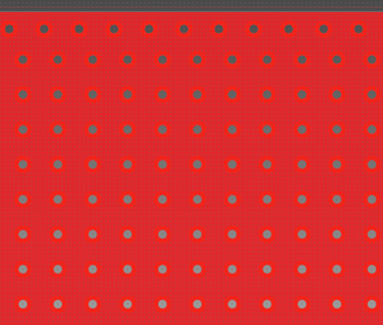
| Both inside and outline | Reinforcing vias are generated both on the inside of the overlapping
area between the specified area fills, and along the outline.
This is illustrated below.
Note The distance from the inside to the outline is controlled by the diameter of the relevant via plus the DRC rule that is specified in the Other Via holes - Other Via holes row in the Via hole sub-tab, in the Conductor Clearance tab of the Rule Editor dialog. Any distance less than this value will result in the removal of a row or column of reinforcing vias from the preview on the canvas. |
||
| Common parameters | This section allows you to specify the padstack, and a powerplane, if applicable. It also allows you to set the spacing between the center points of the vias, and the distance between their center points and the edge of the flooded area. | ||
| Padstack name | Allows you to select the default padstack, or specify a padstack by selecting it from this box. | ||
| Default Padstack | The padstack to be added is automatically determined by the rule area and Via specification of the design rules. | ||
| [Padstack name] | The padstack with the specified name is added. | ||
| Powerplane | If a powerplane exists in the design, then this setting allows you to generate reinforcing vias between the area fills that you specify on the canvas, and the powerplane. | ||
| None | Reinforcing vias are generated between the two area fills that you specify on the canvas. | ||
| (Arbitrary Powerplane) | Reinforcing vias are generated between the area fills that you specify on the canvas, and the specified powerplane. If a powerplane does not exist, then this option cannot be selected. | ||
| Gap between center of vias | Set the spacing between the center points of the vias to be generated. Specify a real number equal to or greater than 0. | ||
| Distance from outline | Specify the distance between the center of the via and the edge of the flooded area. This must be at least half the diameter of the via padstack to ensure that the via is positioned within the flooded area. | ||
| Parameters for inside | This section allows you to specify the pattern of the generated vias, and their position relative to the origin of the design. | ||
| Via generation pattern | Allows you to specify whether the vias are generated in a grid or staggered grid pattern. | ||
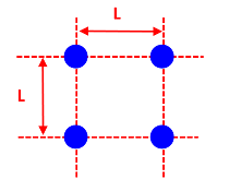
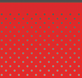
| Grid | The vias are generated in a grid pattern as illustrated below.
"L" represents the gap between the centers of the vias.
An example is shown below of a grid that was created using this grid pattern.
|
||
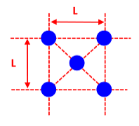
| Staggered grid | The vias are generated in a staggered grid pattern as illustrated
below. "L" represents the gap between the centers of
the vias.
An example is shown below of a grid that was created using this grid pattern.
|
||
| Ref. point of via generation (X) | Set the reference point (X-coordinate) for the vias to be generated from. Set the reference point as a position relative to the origin of the design. The vias are generated form this point, taking into account the values that you set in the Gap between center of vias and Distance from outline fields. | ||
| Ref. point of via generation (Y) | Set the reference point (Y-coordinate) for the vias to be generated from. Set the reference point as a position relative to the origin of the design. The vias are generated form this point, taking into account the values that you set in the Gap between center of vias and Distance from outline fields. |
| Value | Description |
|---|---|
| Execute | The padstacks or reinforcing vias are added to the board according to the parameters specified in the Padstack dialog. |
| Exit | Closes the Padstack dialog without adding padstacks or reinforcing vias to the board. |
