
The following procedure describes how use the Bus Route command to route multiple signals on a single layer.
- On the canvas, select more than two nets that require routing, and then click Net /Route > Routing > Bus Route on the eCADSTAR PCB Editor ribbon. Alternatively, click Net /Route > Routing > Bus Route on the eCADSTAR PCB Editor ribbon, select more than two nets on the canvas, and then click Selection End on the assist menu.
Note
- To select multiple objects, press and hold down the Shift or Ctrl key while you click them.
- Alternatively, if you start the Bus Route command before selecting an object:
- After starting the command, click Home > Select > Select by Area on the eCADSTAR PCB Editor ribbon. Select an area on the canvas by dragging the cursor, and then click Selection End on the assist menu.
- In the Bus Route dialog, specify any required settings.
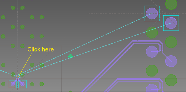
- On the canvas, click a position close to the pins
at the start of the required route. This defines the end routing at
the start of the bus route, and allows you to start sketching a routing
path. An example is provided below.
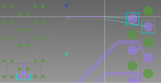
- Create a routing path between the two end points
by clicking positions on the canvas. You can sketch over existing
design items when specifying this routing path. This is illustrated
below.
- Right-click close to the destination pins and select
Finish
on the assist menu. Alternatively, press the Spacebar
on the keyboard. If Single
click finish on snap line is selected in the Design
Settings dialog, then click the snap axis when the target symbol
 is
displayed. Routing is attempted between the specified start and end
points, and any DRC errors that are generated are corrected. If any
segments cannot be routed without errors, then they are left unrouted.
A finished route is illustrated below.
is
displayed. Routing is attempted between the specified start and end
points, and any DRC errors that are generated are corrected. If any
segments cannot be routed without errors, then they are left unrouted.
A finished route is illustrated below.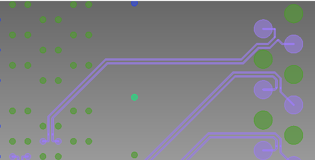
Target objects
The following objects can be selected when running the Bus Route command.
- Unconnected net
- Line
- Pad
- Padstack
Assist menu
The following assist menu items can be specified by right-clicking the mouse while selecting an object.
Command dialog
Note
- A minimum of two signals is required by the Bus Route command.
- If the active layer is not a conductor layer, then it is automatically switched to Conductor-1 when you launch the Bus Route command. You can change the active layer when running the command, before the routing path is displayed.
- You can send items to the Bus
Route dialog from Constraint
Browser using the
 (always
send selection) button.
(always
send selection) button. - To cancel the Bus Route command while it is routing signals, click Ctrl+Break on the keyboard.
