
The following items can be selected by right-clicking while a command is running. Where there are multiple menu items with the same name, a separate description is provided for each item.
Active Layer
Displays the Active Layer dialog.
Apply
The Apply command applies the parameters that you specify. If applicable, the relevant process is executed using the specified parameters.
End Shape
Ends the current operation. The relevant command continues to run.
End Dimension
Ends the current operation. The relevant command continues to run.
End Track
Ends the current operation. The relevant command continues to run.
End Selection
Ends the current operation. The relevant command continues to run.
End Reshape
Ends the current operation. The relevant command continues to run.
Select Segments/Vertices (For Select by Area)
Allows you to select only the segments and vertices that you specify, rather than the whole object.
Placement Side A (For Move command)
The component being moved is placed on side A.
Placement Side B (For Move command)
The component being moved is placed on side B.
Another
After a section is specified, the section to edit is changed
to the section on the other side. This option is available when an area
fill or area is specified.
When an arc is being input, the rotation direction of the arc is reversed.
Series
| Value | Description |
|---|---|
| ON | All objects, including those between the selected track and
the pin to which it connects, are deleted. When the selected track connects to a T-junction, a pad, or an area fill, objects in between are deleted. |
| OFF | The selected objects are deleted. |
Switch between Single and Series
The line segment that includes a via being moved or an end point of a line is moved separately from other lines and vias.
Specify Destination for 3D (For interlayer)
The selection of a layer in 3D view is started.
You can select the destination layer by specifying the cutting plane of
the layer. Only conductor layers can be selected for the destination.
X-axis (For Move)
The dragged object is flipped around the X-axis direction with the drag reference point as the axis.
Mirror Y (For Paste)
The pasted object is flipped around the Y-axis.
Edge Style (For the Lengthen command)
| Value | Description |
|---|---|
| Square | The angle of the segment end of the lengthen pattern is set to 90 degrees. |
| Chamfer | The angle of the route segment end of the lengthen pattern is set to 45 degrees. |
| Semicircle | The shape of the route segment end of the lengthen pattern is set to an arc. If you lengthen a differential pair, then this option is made unavailable. |
Delete Error Mark
The error mark is deleted.
Browse Error Mark
Information about the error mark is displayed.
Insert Arc
An arc is set as the shape to be input next.
Select All Same Name Padstacks
All of the padstacks having the same name as the selected padstack are selected.
Input Start Position
The start position is entered.
Cut and Select by Polygon (For Move)
Makes the cutting shapes available for input.
Cut and Select by Area Fill/Area (For Move)
Makes the area fill or area to be used available for selecting as a cutting shape.
Cut and Add Selection
| Value | Description |
|---|---|
| ON | Lines or area fills are additionally selected for the portion in the area that is cut at the boundary of the area. |
| OFF | Lines or area fills are additionally selected without being cut. |
Control Plane (For Side View)
A specified cutting plane is operated. This item cannot be selected if no cutting plane has been specified.
Flip Horizontally (For Placing Components)
Flips the component about the Y-axis before placing it.
Flip Vertically (For Placing Components)
Flips the component about the X-axis before placing it.
Rotate 90 (For Move/Paste)
The object is rotated 90 degrees around the reference point.
Route from the Other End
The path is fixed and drawn from the other side of the unrouted net to continue specifying the path.
Cancel
The command is terminated without applying any changes that you make in the associated dialog.
Select Section
The selectable objects are limited to sections.
Section (Specify by Area)
| Value | Description |
|---|---|
| ON | Lines and padstacks within the specified area are deleted. |
| OFF | The selected objects are deleted. |
Rectangle
You can input a rectangle area and select all objects with the area.
Arrange Non-Grouped Components
Components that do not belong to any component group are arranged at the outside of the board.
Minimize Cross Connections
The route inside the selected trunk is replaced so that the number of the crossing connections in the trunk is minimized.
Specify Points to Input
On the canvas, specify points to input.
Delete (For Side View)
The cutting plane being operated is deleted.
Delete (For Lengthen)
The lengthen pattern is deleted. Alternatively, use the Unlengthen command.
Change Differential Pair Rule Stack
Specify the differential pair rule stack to be referenced during differential pair routing.
Input Coordinates
The Input Coordinate dialog is displayed.
Next
If there are multiple objects at the selected position, then the current selection is canceled and the next object is selected.
Next Topology Pin Pair
When
If you execute this command while inserting a layer exchange,
then the pin pair rule for the current topology is applied up to the via.
The routing from the via uses the next topology pin pair rule.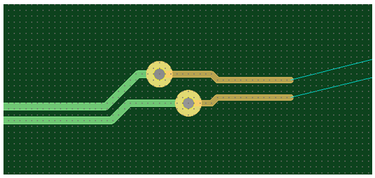
The Next Topology Pin Pair command is made available when one of the following conditions are met.
- There is a topology pin pair before the next Virtual Branch Point (VBP)/pin. This is the VP pin pair.
- There are multiple destinations (VBPs).
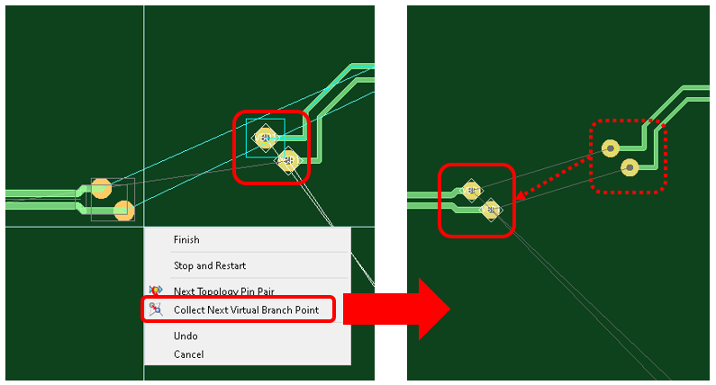
Collect Next Virtual Branch Point
When routing topologies containing Virtual Branch Points (VBPs) in a High Speed environment, the VBPs are collected while routing. This removes the need to place them prior to routing. Alternatively, press C on the keyboard.
This command collects the current target VBPs. Alternatively, press C on the keyboard. It is available only when the current destination is VBP, and either the via pattern is about to be created (the ghost via pattern is shown), or it is just inserted but the next way point has not been created.
- If selected, then the current target VBPs are attached to the vias inside the via pattern, and the via pattern is placed.
- To resume the routing operation, you can select the via pattern.
-
The Collect
Next Virtual Branch Point command collects the next VBPs even
if they are already attached to existing vias.
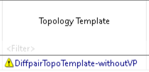
- If
an invalid topology is assigned to a differential pair, then the topology
is shown with a yellow triangle in Constraint
Browser. This may occur if the E-Net construction has changed
since the template was assigned. In this case, the widths and spacings
defined in the topology are not considered. Instead, the standard
widths and spacings for the differential pair are used.
- If the structure of an E-net in a differential pair is updated by adding or removing pins, then it must be re-constructed by clicking Reconstruct E-Net in Constraint Browser.
- If you create a layer exchange when routing a topology, then a Virtual Branch Point (VBP) will snap to the relevant via if within an appropriate distance from it. This occurs even if the topology is not completely routed.
Apply
The specified parameters are applied. If applicable, the relevant process is executed using the set parameters.
Execute
The relevant process is executed using the set parameters.
Rotate by Specified Angle (For Move/Paste)
The dragged object is rotated around the drag reference point. The rotation angle is the value of Angle of rotation on the command dialog.
Rotate by Specified Angle (For Component Symbol)
The component symbol being input is rotated.
Rotate by Specified Angle (For Text)
The characters being input are rotated.
Generate Jumper
A jumper is generated.
Route This End
The end of the selected trunk is routed.
Exit
Exits from the command that is being run.
Input End Position
The end position is entered.
Clear (For Change Reference)
The vertical and horizontal division lines that were input are cleared.
Recover Lost File
If the child board being input is a lost board, its file path is set again to recover the file association.
Enter New Plane (For Side View)
A cutting plane is specified.
Parallel to Dimension
The dimension string is rotated so that it is in parallel to the dimension line.
Vertical to Dimension
The dimension string is rotated so that it is vertical to the dimension line.
Base (Vertical)
Components are vertically aligned.
Base (Horizontal)
Components are horizontally aligned.
Base (Center (Vertical))
Components are vertically aligned to the center.
Base (Center (Horizontal))
Components are horizontally aligned to the center.
Highlight Connected Component (For Lowlight Settings)
Components that are connected to the highlighted signal are also highlighted.
Adjust to Highlighted Figure (For Lowlight Settings)
Zooms the canvas to display the whole highlighted object.
Select Another Net Group (For Lowlight Settings)
If multiple net group candidates are to be highlighted, the target is switched to another net group.
Clear Highlighted Figure (For Lowlight Settings)
Removes the highlight from all objects.
Swap Z-Level
| Value | Description |
|---|---|
| Swap with Upper Component | The Z-level and the position in height direction of the selected
component are replaced with those of a die component that satisfies
the following conditions.
|
| Swap with Lower Component | The Z-level and the position in height direction of the selected
component are replaced with those of a die component that satisfies
the following conditions.
|
Route Ends
All ends of the selected trunk are routed.
Unroute Ends
The ends of the selected trunk are unrouted.
Selection End
Indicates that you have selected the required item. When selecting multiple items using the Ctrl key, click Selection End on the context menu to indicate that you have selected the final item. Alternatively, double-click the final item.
Arrange All Components
All components are arranged at the outside on the board.
Move to Other Layer
The Move To dialog is displayed. Select the layer as the destination of move.
Copy to Other Layer
The Copy To dialog is displayed. Select the layer as the duplication destination.
Mirror (For Move and Duplicate (Move))
Moves components and objects to the opposite side of the board while maintaining the relative position.
Polygon
You can input a polygonal area and select all objects with the area.
Always Horizontal
Sets an angle of the dimension text attributes to horizontal.
Always Vertical
Sets an angle of the dimension text attributes to vertical.
Stop and Restart (For Trunking)
This menu item fixes the route that has been drawn and
starts input of a new trunk object that has the same net configuration.
Use this menu item to avoid obstacles during trunk routing.
Finish (During data selection)
The data for the active operation is applied, if allowed, or a warning message is shown.
Finish Here
When using the Add Route command, the routing pattern is terminated at the current location on the canvas. To complete the routing, click Finish instead.
Drag Reference Point (Vertex)
The drag reference point is changed to a vertex of the specified object. The vertex closest to the specified point becomes the reference point. In Snap mode, the specified point becomes the reference point.
Drag Reference Point (Point)
The drag reference point is changed to the specified object.
Drag Reference Point (Center)
The drag reference point is changed to the center of the specified object. In Snap mode, the specified point becomes the reference point.
Drag Reference Point (Point) (For Scale by Area)
The drag reference point is changed to the specified object. In Snap mode, the specified point becomes the reference point.
Drag Reference Point (Center) (For Scale by Area)
The drag reference point is changed to the center of the specified area to be scaled.
Compose
The selected routes are converted to trunk routes. An attempt is made to compose all routes, including curved routes into trunks.
- Some items may fail to compose into a trunk item. This may occur if the selected items do not fully match the criteria of the design rules for track widths and spacing, or do not comply with the composition parameters that are set in the Design Settings dialog.
- The modified route segments of a decomposed trunk cannot be composed back into a trunk item if they no longer match the criteria of the design rules for track widths and spacings, or do not comply with the composition parameters that are set in the Design Settings dialog.
- When composing trunks for differential pairs that use topology templates, the following restrictions apply.
Curve
Allows you to curve a section of a trunk which contains an uncurved corner. Multiple trunk segments can be curved simultaneously. This command is made unavailable if a trunk or track within a trunk is not selected, or if none of the items selected on the canvas meet the required criteria. See: Curve.
Uncurve
Allows you to uncurve a section of a trunk which contains an curved corner. Multiple trunk segments can be uncurved simultaneously. See: Uncurve.
Decompose
The selected routes in the trunk are converted to regular routes. All selected trunks are decomposed, including curved trunks.
- If you decompose a straight segment, then any adjacent curved trunk segments are also decomposed.
- If you decompose trunks for differential pairs that use topology templates, then restrictions apply if the trunk is recomposed. See: Impedance Balanced Routing (IBR).
Rotate 270 (For Move/Paste)
The object is rotated 270 degrees around the reference point.
Input (For Subtract)
Zoom Net
All tracks in the net where a path is being specified are zoomed in on.
Specify Net
Specify the net that is added to the object to be input.
Select the menu. On the canvas, specify the object to which the net has
been added.
Specify Net (For Move)
Specify the net that is added to the object to be moved.
Select the menu. On the canvas, specify the object to which the net has
been added.
* This command has precedence over Fix net
on the command dialog.
Clear result display
For routing that is performed by the Autorouter command, the currently-displayed results are hidden.
Maintain Length (For the Lengthen command)
| Value | Description |
|---|---|
| Off | The route length is not adjusted. This is the default setting. If you select Off after selecting Meet Constraints, then the adjustment to the route length is reversed that is made when you select Meet Constraints. |
| Meet Constraints | The route length is adjusted to meet the constraints. It is recommended that this command is used after you manually adjust the size of the lengthen pattern using the grab handles. This command is only available in a High Speed environment. |
| Current Length | The route length is adjusted without changing the existing length of the routing pattern. |
Update Widths/Spacings
The selected trunk is updated so that it complies with
the track width and clearance specified by the design rules.
- Trunk segment (Track in trunk).
- Via pattern (via in trunk or spoke track).
Execute this command from the assist menu of the Regulate
Trunk command.
Reset Padstack on Active Layer
| Value | Description |
|---|---|
| ON | The shape of the selected padstack's active layer is reset
to that of the library. When the hole layer is the active layer,
the hole diameters are reset. When the shape resulting from the process is the same as the library shape, the padstack becomes an edit-less padstack. |
| OFF | The shape of the selected object that has already been edited
is reset to that of the library. When the object shape resulting from the process is the same as the library shape, the object becomes an edit-less object. |
Fix Pad Selection
The selected pad is applied.
Another Section
The section to edit is changed to the section on the other side. This option is available when an area fill or area is specified.
Reverse (For Side View)
The direction of the cutting plane being operated is flipped.
Flip (For Lengthen)
The first bump direction of the Lengthen command is flipped.
Extract Via Pattern
The via patterns in the selected trunk are deleted.
Insert Via Pattern
A via pattern is inserted into the selected trunk.
Hide
The selected mechanical data is hidden.
Rotate 180 (For Move/Paste)
The object is rotated 180 degrees around the reference point.
Rotate 180 (For Lengthen)
The start point is swapped for the end point. The bump direction as seen from the start point is maintained.
Execute from File (For Component Symbol)
The Execute from File dialog is displayed. Specify the text file containing the component symbol character strings for the references and click OK. The component symbols are input according to the contents of the file.
Component Selection End
The selected components are applied.
Divider (Vertical) (For Change Reference)
In Restart on vertically divided board or Restart on board divided by grid mode, a horizontal baseline is added.
Divider (Horizontal) (For Change Reference)
In Restart on horizontally divided board or Restart on board divided by grid mode, a vertical baseline is added.
Closed Line
A straight line that connects the start and end points is generated to create a line of a closed object. This ignores the Angle Lock setting.
Select Another Track (For Side View)
This can be specified in line follow-up mode. The conductor line to be followed is specified again.
Search for Shortest Unrouted Net
When no net is selected, the shortest unrouted net is selected and zoomed in on.
Zoom Unrouted Net
The unrouted net where the path is being specified is zoomed in on.
Arrange Unplaced Components
All unplaced components are arranged at the outside on the board.
Select Mechanical Data
Select the mechanical data from the canvas.
Select Area Fill/Area to Input
Select an area fill or area on the canvas by dragging the mouse, and add it without changing its shape.
Select Matching Components
For the Change Footprint command, the components are selected on the canvas that are identified using the Same part function.
Mode (For the Lengthen command)
| Value | Description |
|---|---|
| Accordion | Lengthening is added to a selected routing pattern using the
accordion style. This is illustrated
below.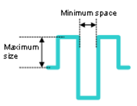 |
| Trombone | Lengthening is added to a selected routing pattern using the
trombone style. This is illustrated
below. |
Switch Leader Dimension
Toggles between available and unavailable of dimension strings.
Undo
Reverses the effects of the last operation that is executed.
Redo
Re-executes the last operation that is executed.
Delete All Measures (For Measure)
All measures displayed on the canvas are deleted.
Delete Single Measure (For Measure)
Select a single measure on the canvas to delete it.
By Line (For Subtract)
When object to subtract is set to Input shape, lines are input as shapes.
Select by Line
You can input a line and select only the following objects that are in contact with the line.
- Conductor line
- Pin object
- Unrouted net
- Padstack
Follow Track (For Side View)
When this is set to ON, line follow-up mode is entered. When a conductor line is specified, the cutting plane moves along the specified line.
Select Signal to Add to List
The signal of the object selected on the canvas is added to Signal list.
Restart reference designator (For Change Reference)
In Restart on board divided by grid mode, set Grid ID and Format to reset references.
By Frame (For Subtract)
When Object to subtract is set to Input shape, areas are input as shapes.
Select Antenna in Area
You can input a polygonal area and select all antennas that come in contact with the area.
Clear Specified Area
You can delete the area that was input and clear selection of objects with the area.
Specify Area Mode
Select by Area
You can input a polygonal area and select all objects that come in contact with the area.
Y-axis (For Move)
The dragged object is flipped around the Y-axis direction with the drag reference point as the axis.
Put Side A to Top Side
The board is moved with Side A facing up in 2D view.
Put Side B to Top Side
The board is moved with Side B facing up in 2D view.
Add All Layers (For DXF Export)
Adds rows for all layers to the Layer to convert box.
Add Visible Layers (For DXF Export)
Adds rows for all visible layers to the Layer to convert box.
Add Rows (For DXF Export)
Displays the Select Layer dialog, enabling you to select the layers to be added to the Layer to convert box.
Delete Rows (For DXF Export)
Deletes all selected rows from the Layer to convert box.
