
The Bus Route command is a semi-automatic routing tool which provides fast, error-free routing of multiple signals or buses on a single layer. It is launched by clicking Net /Route > Routing > Bus Route on the eCADSTAR PCB Editor ribbon. Routing is done in 45-degree segments, and uses the settings that you specify in the Bus Route dialog, and in the Bus Route section in the Design Settings dialog.
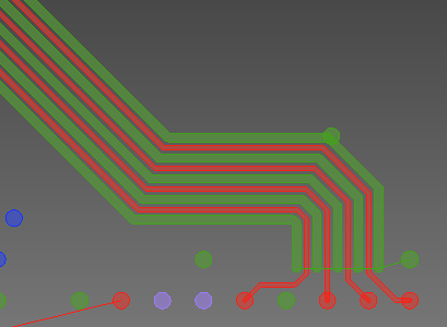
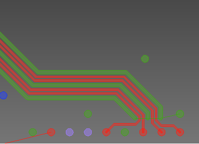
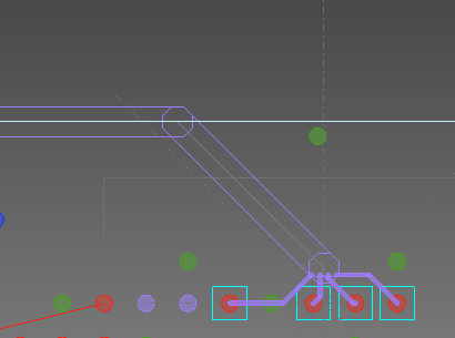
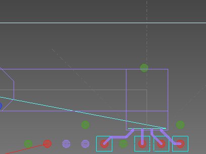
Any combination of single-ended signals or differential pairs can be routed. For the connections or nets which you select on the canvas, this command allows you to sketch an approximate path on the canvas. You can sketch over existing design items when specifying this routing path. The selected items are then resolved as routes, if possible, in the direction of the specified routing path, and without DRC errors. Obstacles are automatically avoided if they are not part of the set of signals that are being routed. If necessary, individual routes within the selection are split to avoid obstacles.
The width of the routing path is the minimum width required to include all selected signals. This includes the appropriate spacings for signals, as well as any additional spacing, and spacing reserved for shield routing that is specified in the Bus Route dialog.
When you complete the sketched routing path by clicking Data End, or by clicking an axis marker, routing is attempted between start and end points of the sketched path, and any DRC errors that are generated are corrected. If any segments cannot be routed without errors, then they are left unrouted.
This command significantly reduces the routing time for bus routing patterns on a single layer. However, the density and number of obstacles encountered will affect routing performance. It is therefore recommended to use this command before adding large numbers of obstacles to the design.
Auto minimize crossed connection
| Value | Description |
|---|---|
| ON | If necessary, the order of the signals in the routing pattern is automatically changed. This minimizes cross connections between the nets, and improves the completion of the end routing. |
| OFF | The order of the signals in the routing pattern is not changed. |
Remove incompletes
| Value | Description |
|---|---|
| ON | When the bus routing is completed, any routing patterns are deleted that cannot be connected to the end point. The whole of the signal path is removed, and a gap will remain in this position. |
| OFF | When the bus routing is completed, routing patterns are not deleted that cannot be connected to the end point. |
Guide settings
| Value | Description |
|---|---|
| Settings | Displays the Bus Route section in the Design Settings dialog. This allows you to specify the guide parameters for the Bus Route command. These are used when specifying the route of the signals on the canvas. |
Differential Pair
Allows you to specify that additional space or a shield signal is added to differential pairs that are routed using the Bus Route command. Additional space and shield signals are not applied to the end routing. The differential pairs that you specify must contain at least two signals.
Additional space
| Value | Description |
|---|---|
| Real number between 0 and 100.0 mm (inclusive). | Specify an additional clearance between differential pairs
and other routes. The additional space is added on either side
of the differential pair. Additional space around differential
pairs can only be added if sufficient space is available around
the obstacles on the board. If
obstacles force the repositioning of the differential pair after
the initial sketch, then the spacings are used that are specified
in the DRC
Settings dialog.
|
Shield signal
| Value | Description |
|---|---|
| Signal name (Power/ground nets). | Select the net name of the shield pattern that is added between
differential pairs and other routes. The shield pattern that you
select is added to both sides of the differential pair. Only nets
with the power/ground attribute
can be selected.
|
Single Ended
Shield after signal number
| Value | Description |
|---|---|
| Integer between 0 and 99. | Allows you to add a selected shield pattern to both sides of
the signals that you specify. The selected shield pattern is added
at the interval specified in this field. For example, if you specify
'1' in this field, then the shield pattern is added to every signal
in the bus. This is illustrated below.
Note The selected shield pattern is not applied to the end routing. |
Shield signal
| Value | Description |
|---|---|
| Signal name (Power/ground nets). | Select the net name of the shield pattern that is added between the selected single ended signals. The shield pattern that you select is added to both sides of the signal, at the interval specified in the Shield after signal number field. Only nets with the power/ground attribute can be selected. If a net name is not selected, then a shield signal is not added. |
- A minimum of two signals is required by the Bus Route command.
- If the active layer is not a conductor layer, then it is automatically switched to Conductor-1 when you launch the Bus Route command. You can change the active layer when running the command, before the routing path is displayed.
- You can send items to the Bus
Route dialog from Constraint
browser using the
 (always
send selection) button.
(always
send selection) button. - To cancel the Bus Route command while it is routing signals, click Ctrl+Break on the keyboard.
