
Checking the Current Distribution
This topic describes how to check the current distributions as the result of DC analysis.
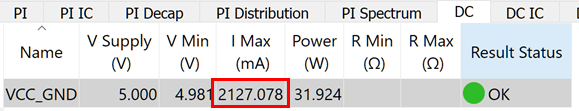
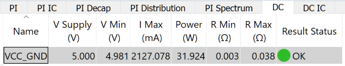
- In the eCADSTAR PI/EMI Analysis module, Power Bus view, select the DC tab.
- Check the maximum amount of current, shown by the I Max value. Usually, the I Max value is close to the current value of a component to be set as the supply source.
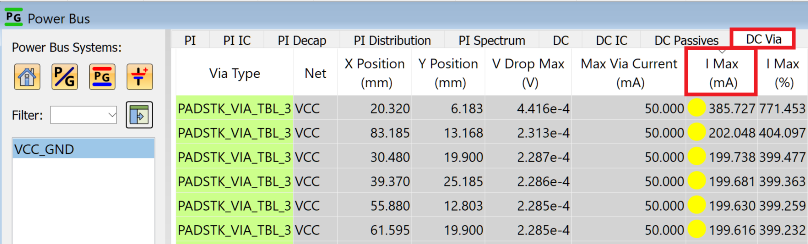
- To check the maximum current for each via, select the DC Via tab, and click the column label of the I Max (mA) column. The values are sorted in descending order.
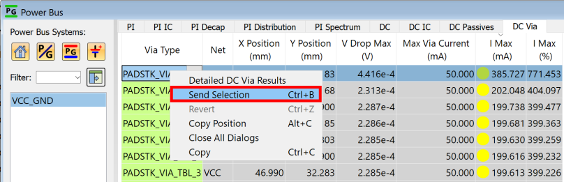
- By selecting each row and executing the Send Selection command, you can check the via position on the canvas in eCADSTAR PCB Editor.
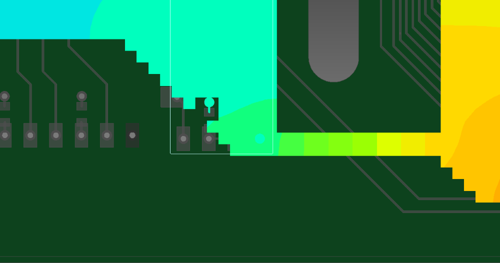
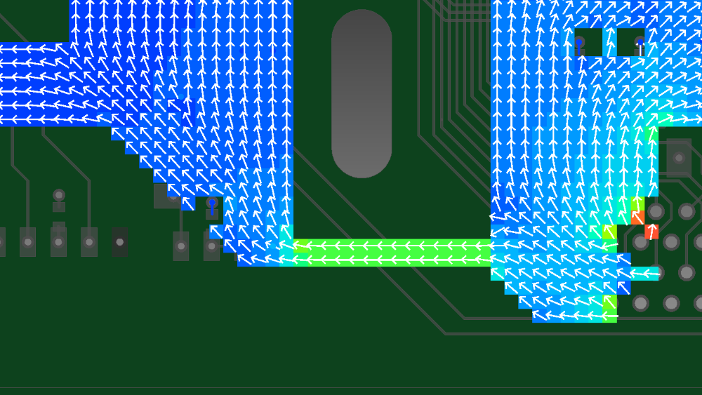
- In the PI/EMI Analysis Heatmap dialog, set the Map type value to Current density. The current density distribution is displayed on the canvas.
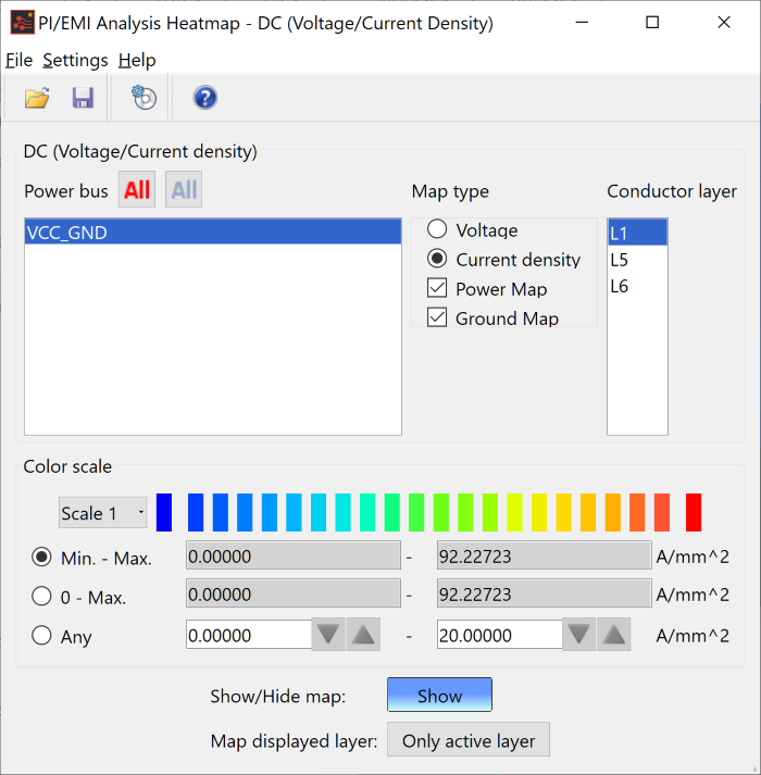
- To display the map for only the selected Conductor layer, select Only active layer in the Map displayed layer field in the PI/EMI Analysis Heatmap dialog.
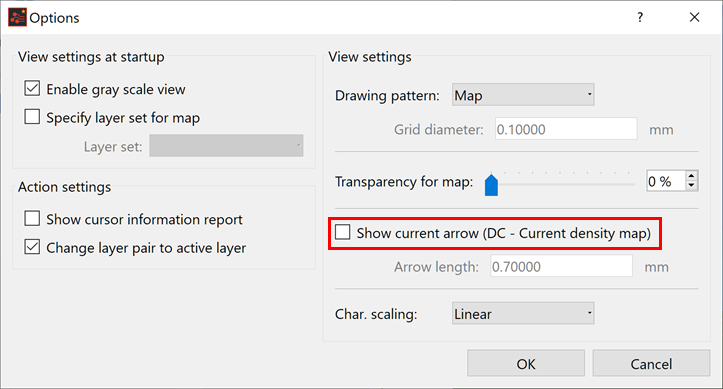
- To show the current direction using arrows:
- On the menu bar of the PI/EMI Analysis Heatmap dialog, click Settings > Options. The Options dialog is displayed.
- In the Options dialog, select the Show current arrow (DC - Current density map) check box. For further information on this dialog, see the Online Help in eCADSTAR.
Checking the Current Distribution
- On the toolbar in the PI/EMI Analysis module, click
 DC-R
Extraction. This command calculates the DC resistance values
between individual supply pins. When the calculation is completed,
the DC tab of the Power
Bus view opens and the result is displayed.
DC-R
Extraction. This command calculates the DC resistance values
between individual supply pins. When the calculation is completed,
the DC tab of the Power
Bus view opens and the result is displayed.
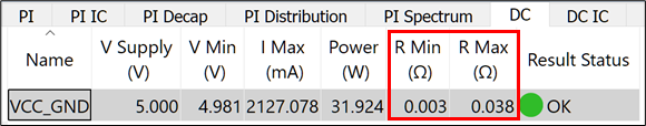
- In this tab, you can check the minimum and maximum resistance values between the source pin and load pin.
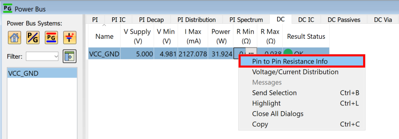
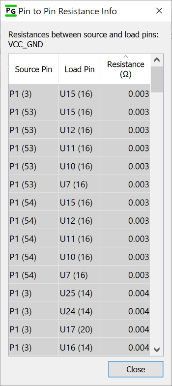
- Right click, and select to Pin to Pin Resistance Info on the assist menu. The Pin to Pin Resistance Info dialog is displayed. This allows you to check the resistance value for each pin.
You have now completed the eCADSTAR Power Integrity/EMI Analysis training, and can close all eCADSTAR applications.
