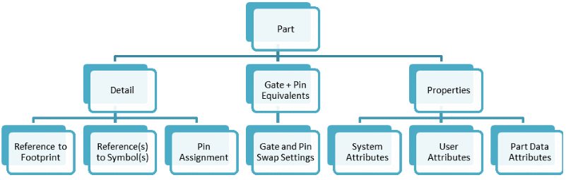
Parts are the highest level in the structure of a component and are identified by a unique Part Name. The structure of the main information included in part definitions is shown below.
Part Properties
Part definitions include properties that are used in schematic and PCB design. These are displayed in the Part Editor Panel: Properties tab.
System Part Attributes
The System Part Attributes shown below directly affect how eCADSTAR tools handle the part during design operations.
| System Part Attribute | Definition |
|---|---|
| Value | The basic value for a passive component. For example, a value of “10” could be specified for a 10 Ω resistor. |
| Device Type | Components that only conduct DC or AC energy, such as resistors, capacitors, inductors and diodes are specified as Passive. Components such as digital ICs that supply energy to the signals that they drive are specified as Active. |
| Passive Type | Passive types include Capacitor, Resistor, Inductor, Diode or Other Passive. Setting Passive Type to Undefined means the component is not passive. A value of None means any Passive Connectivity is ignored. |
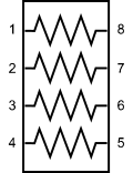
| Passive Connectivity |
For passive component packs, this defines the internal pin-to-pin connectivity as pin pairs. For example, the 8-pin resistor pack shown below, which contains four resistors, would have Passive Connectivity set to “1-8 2-7 3-6 4-5”.
|
| Allow Testpoints | YES means the pins of the part can be treated as testpoints. NO means they cannot. This makes it possible to assess testability by knowing where it is possible to probe, without adding extra, dedicated testpoints. |
| Solder Method | Reflow, Single Reflow or Any can be specified. When the component is placed on a PCB and a design rule check is performed, this value is compared to the method specified for the layers on which it is soldered. A DRC error is reported if the values conflict. |
| Use in Schematic | YES or NO can be specified. Selecting YES back-annotates information for the relevant part from eCADSTAR PCB Editor to eCADSTAR Schematic Editor when you execute the Back Annotation command in eCADSTAR Schematic Editor. |
| Use in Layout | YES or NO can be specified. Selecting YES forward-annotates information for the relevant part from eCADSTAR Schematic Editor to eCADSTAR PCB Editor when you execute the Forward Annotation command in eCADSTAR PCB Editor . |
| Use in Parts List | YES or NO can be specified. Selecting YES means that the relevant part appears in parts lists that you generate from eCADSTAR applications. |
| Comment | Allows you to associate a comment with a part. In eCADSTAR PCB Editor, the value that you specify is displayed in the Comment field in the Properties Panel when you select the part on the canvas. In eCADSTAR Schematic Editor, the value that you specify is displayed in the Comment field in the Properties Panel when you select the part on the canvas. |
User Part Attributes
The User Part Attributes shown below contain details about the part, but do not directly affect how eCADSTAR handle it. In addition to the standard set, there are spare attributes that you can use for your own purposes. User-defined attributes are defined in the Attribute Manager dialog.
| User Part Attribute | Definition |
|---|---|
| Part Number | The part number in the format used by your organization. A part number is not necessarily unique within the library. For example, multiple part sourcing can mean a single part number references multiple manufacturer part numbers. |
| Manufacturer | The manufacturer of the part. |
| Manufacturer Part Number | The part name or number used by the manufacturer. This can differ from the part number, as some designers use internal part names or numbers in their circuits. |
| Vendor Reference | When you use eCADSTAR to search online for parts by vendor reference, this is the name to use as a search term. |
| Vendor | The preferred vendor for the part. |
| Tolerance | For parts where tolerance is relevant, for example resistors or capacitors, this field allows you to specify the tolerance. For example, "10%", "+/-5%", "+5%/-2%". |
| Wattage | The power rating of a component such as a resistor, for example “100mW”. This is usually the maximum power rating. |
| Frequency | A frequency value or range. For example, the frequency for an oscillator part could be set to “100MHz”. |
| Voltage Rating | The operating voltage. For example, a 10uF tantalum capacitor might have a Voltage Rating of “10V”. This is usually the maximum voltage. |
| Current Rating | The nominal current rating that is specified for a part. |
| Maximum Operating Temperature | The maximum operating temperature of the component. This value is typically specified, in degrees Celsius, for Integrated Circuits (ICs) in various forms, such as Maximum Junction Temperature or Maximum Ambient Temperature.You decide what to use for this value. For example, an FPGA (Field Programmable Gate Array) might be assigned a Maximum Operating Temperature value of “105C”. |
| Minimum Operating Temperature | The minimum operating temperature of the component. This value is typically specified in degrees Celsius for Integrated Circuits (ICs) in various forms, such as Minimum Ambient Temperature. You decide what to use for this value. For example, a device might be assigned a Minimum Operating Temperature value of “-20C”. |
| Package Type | The package type as specified by a vendor or manufacturer, or in any other format. For example, PDIP, QFP or TQFN. |
| Dimensions | The dimensions of the package, for quick-reference information only. This value is not used for DRC checking. For, example “10mm x 20mm”. |
| Terminal Pitch | The basic pitch of the component pins, balls, lands or other terminal types. If the pitch varies within a part, then you can decide which value to assign here. For example, “0.8mm”. |
| Mounting Type | This field is most commonly specified for connectors. For example, Surface Mount, Right Angle or Through Hole. |
| Gender | This field is typically specified for connectors. The supplier usually indicates whether the component, and this attribute value, should be “Male” (usually the plug side”) or “Female” (usually the receptacle side). |
| Number of Rows | For connectors, the number of rows of pins. For example “1” or “2”. |
Data Properties
The Data Properties shown below are automatically assigned values when you create or edit a part. These attributes specify who created or modified the part, and its creation and modified dates. For example, if you are signed in as user “Wells” when you edit a part, then “Wells” is set as the value for Modified By.
| Part Data Property | Definition |
|---|---|
| Created by | The name of the user who created the part. |
| Created Date | The system date and time that the part was created. |
| Modified By | The name of the user who last modified the part. |
| Modified Date | The system date and time that the part was last modified. |
Part Acceptance
The Part Acceptance section indicates whether a part is approved for general use. If a part is unapproved, then you can enter a reason. Unapproved parts can still be added to a design.
| Setting | Definition |
|---|---|
| Part Acceptance Status | Indicates whether a part has been accepted for general use. Allowed values are Approved and Unapproved. |
| Part Acceptance Reason | The reason for setting the Part
Acceptance Status to Unapproved.
The following are possible reasons.
|
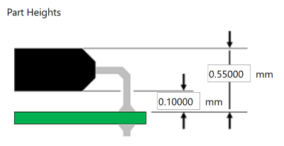
Part Heights
The Part Heights section contains basic information on the top (maximum) and bottom (standoff) heights of a part, relative to its mounting surface.
| Setting | Definition |
|---|---|
| Maximum Height | The height of the top of a component, relative to its mounting surface. This value is shown as 0.55000 in the following image. |
| Standoff Height | The height of the bottom of a component, relative to its mounting surface. This value is shown as 0.10000 in the following image. |