
The Properties panel displays
the properties associated with an object that is selected on the eCADSTAR Schematic Editor
or Symbol Editor canvas,
and allows you to change the properties where applicable. Toggle on the
Properties panel by clicking View
> Display >  Property.
Alternatively, click Property on the
status bar.
Property.
Alternatively, click Property on the
status bar.
- When multiple objects of the same type are selected, the same items are displayed as when a single object is selected.
- Properties of multiple objects can be changed simultaneously.
- For the Coordinates, User Attributes and SPICE Attributes properties, click either "+" or "-" to toggle the display of child objects. The specified setting is saved until the application is restarted.
Component properties are displayed in the following order.
- System defined properties, not including SPICE related properties.
- User defined attributes
- SPICE related properties
If you right-click a row which has an attribute defined as a hyperlink in the Attribute Manager dialog, then you can launch the hyperlink by clicking Open Hyperlink on the assist menu. This is also possible in eCADSTAR Schematic Viewer. If multiple cells are selected that have different values or If a hyperlink is not specified, then this command is made unavailable. The hyperlinks are launched in your default browser.
| Item | Description | |
|---|---|---|
| Property | Shows the properties associated with the object that you select on the canvas. User-defined attributes are also listed in eCADSTAR Schematic Editor. User-defined attributes are specified in the Attribute Manager dialog, in eCADSTAR Library Editor. The relevant values are set in the Library Editor Panel: Parts tab, or the Part Editor Panel: Properties tab, User Part Attributes section. | |
| Value | Shows the values associated with each property. The type of cell varies depending on the associated property. Set a value as follows for each type of cell. properties cannot be set when a command is running. | |
| Numerical field | A cell containing a real number or integer. Click the cell to set a value. | |
| Box | A cell containing multiple options. Select a value from the box. | |
| Text pad | A cell with a character string. Click the cell to enter a character string to the text pad. | |

|
Enter a value directly, or select a value from the dialog that
is displayed by clicking . |
|
| Control |

|
For certain rows, the control column determines how the Value column behaves when updated. Details are provided on a row-by-row basis below. |
- For items that are split over multiple sheets, such as net sub circuits or multiple gated items: when adding a value, it is added only to the selected item, and not to the associated ones. For example, if you apply a design rule stack value to a sub circuit on sheet 001, it is not automatically applied to a sub circuit on sheet 002. It is recommended to add the value in Constraint Browser, which applies it to all relevant sub circuits, and gates. Alternatively, enter these values manually for each sheet and item. However, for a multi-gated part, the Fitted attribute applies to all gate components.
- If you change the Reference Designator value for a gate component, then the value is updated for all parts in the design with that Reference Designator value.
The properties displayed in the Properties panel vary depending on the object that you select on the canvas. A selection of important properties are shown below.
When a property viewer is selected
When a simulation frame is selected
When a component is selected
| Item | Description | ||
|---|---|---|---|
| Property | The properties are listed that are associated with the component
selected on the canvas. If you specify SPICE attributes in the
Library
Editor Panel: Parts Tab or the Part
Editor Panel: SPICE Tab for a part, then the specified values
are shown in the relevant SPICE columns when the part is added
to the canvas. For further information on SPICE attributes, see:
Understanding
SPICE Controller.
Note The SPICE attributes that you specify in this panel are not added to the library. When simulating with parts, it is recommended to add them to the library instead. However, this is not necessary when simulating only with symbols. |
||
| Reference Designator | Specify the reference of the component. If you specify a Reference Designator value that already exists on any sheet in the design, then a warning dialog is displayed which shows the duplicate value. However, it is not displayed if the value exists within a block in the design.
If you update this value for a gate component, then the value is updated for all parts in the design with that Reference Designator value. Gate components are components that have the same Reference Designator value. Note The warning dialog is not displayed if a duplicate Reference Designator value is assigned to empty gates or empty power boxes. |
||
| Gate Number | For Gated Components, the Gate Number will be shown. This corresponds to the Gate selected on the sheet. For components that do not consist of any gates, No value will be shown in this row. | ||
| Coordinates | Allows you to set the X and Y coordinates of a component selected on the
canvas in eCADSTAR Schematic Editor, including a part, connector or block. In Symbol Editor, these values are also editable. Click either "+" or "-" to toggle the display of the X and Y rows. The specified setting is saved until the eCADSTAR application is restarted. Either type or paste a numeric value in the relevant box. If a component cannot be moved to the specified coordinates because of a net or component conflict, for example, then the coordinate values are not changed. If multiple objects of the same type are selected, then their coordinate values cannot be set. Note
|
||
| X | Specify the coordinate of the component in the X direction. | ||
| Y | Specify the coordinate of the component in the Y direction. | ||
| Angle | Allows you to specify the angle at which the component is displayed on the eCADSTAR Schematic Editor canvas. | ||
| Mirror | Specify whether a selected component, connector or block is flipped in the vertical plane.
|
||
| Scale | Allows you to specify the scale of the component. | ||
| Part name | Displays the part name for a selected component.
|
||
| Symbol name | Allows you to change the symbol name for a selected component, connector or block. Select a value using the Change Symbol dialog. This is displayed when you point the cursor in this box, and then click the displayed |
||
| Symbol Alternate | For a selected component or connector, you can select an alternate symbol name if available. Select a value using the Change Symbol dialog. This is displayed when you point the cursor in this box, and then click the displayed |
||
| Number of Pins | Displays the number of pins on the component. | ||
| Component Type | Displays the component type. | ||
| Bit Count | The total number of bits associated with the component. | ||
| Color <DEF> | Allows you to specify the color of the component on the schematic
sheet. Click to display
the Select color dialog. |
||
| Instance Net Label | Displays the instance net label associated with the component. | ||
| Comment | Displays comments that are associated with the component. | ||
| Block Name | Displays the name of the block | ||
| Hierarchy Type | Shows whether the block symbol is a definition block, which can be reused in the design. This is specified in theBlock Symbol dialog. | ||
| Multi-Instanced | The new block symbol is a definition block. It can be reused in the design by selected it in the Add Block, or Change Block command. When it is updated, all instance blocks that are added to the design based on this block are also updated. To do this, select Check Hierarchy Update and then select Update All Instances or Update Instance. | ||
| Single-Instanced | The new block symbol is used only on the displayed canvas. It cannot be reused in the design by selecting it in the Add Block or Change Block command. | ||
| Value | Displays the value that is specified for the component in the Library Editor Panel: Parts tab, or the Part Editor Panel: Properties tab, Value column. | ||
| Description | Displays the description of the component that is specified in the Library Editor Panel: Parts tab, Description column. This might include the type of component, and its specification. For a selected block, you can edit this value. | ||
| Component Group | Define the name of a component group in this cell to associate the component with it. When you forward annotate into eCADSTAR PCB Editor, the specified component group appears in the Component Group Settings dialog. Component groups allow you to move multiple components as a single group on the eCADSTAR PCB Editor canvas. | ||
| Placement Group | Define the name of a placement group in this cell to associate the component with it. The specified placement group is added to eCADSTAR PCB Editor when you forward annotate. Placement groups are used by the Gather Components command. | ||
| Fitted | Specify whether a component is mounted on the board by selecting YES or No. Selecting YES specifies that it is mounted on the board. For a multi-gated part, the status of all gate components is updated. | ||
| Reference Designator Prefix | Displays the prefix for the reference designator of components. This is specified in the Library Editor Panel: Parts tab, Reference Designator Prefix column. | ||
| Start Value for Reference Designator | For a selected block, this field allows you to specify the start value of the reference designators of its associated components. This value is applied instead of the value in the Sheet Settings dialog, Properties tab, Start Value for Reference Designator field. | ||
| Part Number | Displays the part number of the component that is specified in the Library Editor Panel: Parts tab, or the Part Editor Panel: Properties tab, Part Number column. | ||
| Manufacturer | Displays the Manufacturer for the component that is specified in the Library Editor Panel: Parts tab, or the Part Editor Panel: Properties tab, Manufacturer column. | ||
| Manufacturer Part Number | Displays the Manufacturer Part Number for the component that is specified in the Library Editor Panel: Parts tab, or the Part Editor Panel: Properties tab, Manufacturer Part Number column. | ||
| Vendor Name | Displays the Vendor Name that is associated with the component in the Library Editor Panel: Parts tab, or the Part Editor Panel: Properties tab, Vendor Name column. | ||
| Vendor Reference | Displays the Vendor Reference that is associated with the component in the Library Editor Panel: Parts tab, or the Part Editor Panel: Properties tab, Vendor Reference column. | ||
| Tolerance | Displays the tolerance for the setting in the Value cell. The Tolerance setting is specified in the Library Editor Panel: Parts tab, or the Part Editor Panel: Properties tab, Tolerance column. | ||
| Wattage | Displays the electrical power of the component, expressed in watts, that is specified in the Library Editor Panel: Parts tab, or the Part Editor Panel: Properties tab, Wattage column. | ||
| Frequency | Displays the frequency of the component that is specified in the Library Editor Panel: Parts tab, or the Part Editor Panel: Properties tab, Frequency column. | ||
| Voltage Rating | Displays the voltage rating of the component that is specified in the Library Editor Panel: Parts tab, or the Part Editor Panel: Properties tab, Voltage Rating column. | ||
| Current Rating | Displays the current rating of the component that is specified in the Library Editor Panel: Parts tab, or the Part Editor Panel: Properties tab, Current Rating column. | ||
| Max. Operating Temperature | Displays the maximum operating temperature of the component that is specified in the Library Editor Panel: Parts tab, or the Part Editor Panel: Properties tab, Maximum Operating Temperature column. | ||
| Min. Operating Temperature | Displays the minimum operating temperature of the component that is specified in the Library Editor Panel: Parts tab, or the Part Editor Panel: Properties tab, Minimum Operating Temperature column. | ||
| Dimensions | Displays the dimensions of the component that are specified in the Library Editor Panel: Parts tab, or the Part Editor Panel: Properties tab, Dimensions column. | ||
| Package Type | Displays the type of package for the component that is specified in the Library Editor Panel: Parts tab, or the Part Editor Panel: Properties tab, Package Type column. A package type has a defined set of physical dimensions that the component has to conform to. Typically, the pitch spacing, height and general shape of the component is defined. for each package. | ||
| Terminal Pitch | Displays the distance between the pins on the component that are specified in the Library Editor Panel: Parts tab, or the Part Editor Panel: Properties tab, Terminal Pitch column. | ||
| Mounting Type | Displays the mounting type that is specified in the Library Editor Panel: Parts tab, or the Part Editor Panel: Properties tab, Mounting Type column. Mounting types for a component might include "through-hole" or "surface mount". | ||
| Gender | Displays the gender of the component that is specified in the Library Editor Panel: Parts tab, or the Part Editor Panel: Properties tab, Gender column. The gender of a component can be specified as "male" (plug) or "female" (socket). | ||
| Number of Rows | Displays the number of rows of pins on the component that is specified in the Library Editor Panel: Parts tab, or the Part Editor Panel: Properties tab, Number of Rows column. | ||
| Part Class | Displays the class that is specified for the part in the Library
Editor Panel: Parts tab, Part Class
column. The following values can be specified.
|
||
| Part Acceptance Status | Displays the approval status of the component. This is specified
in the Library
Editor Panel: Parts tab, Part Acceptance
Status column. The following values can be specified.
|
||
| Part Acceptance Reason | Displays the reason for non-approval of the part that is entered in the Library Editor Panel: Parts tab, Part Acceptance Reason column. | ||
| Device Type |
You can change the Device Type of the selected component.
|
||
| Passive Type | Displays the type of passive component. These are specified
in the Library
Editor Panel: Parts tab, or the Part
Editor Panel: Properties tab, Passive
Type column. The following values may be displayed.
|
||
| Passive Connectivity | If this value is specified in the Library Editor Panel: Parts tab, or the Part Editor Panel: Properties tab, then a list of connected passive pin pairs are displayed that are separated by the "space" character. | ||
| Allow Testpoints | Displays whether testpoints can be generated for the part. This value is specified in the Allow Testpoints field in the Library Editor Panel: Parts tab, or the Part Editor Panel: Properties tab. | ||
| Solder Method | Displays whether the solder method for the part is restricted to "Reflow" or "Single Reflow", or whether it is set to "Any", to allow any method of soldering. This value is specified in the Solder Method field in the Library Editor Panel, Parts tab, or the Part Editor Panel, Properties tab. | ||
| Use in Schematic | Displays whether the part can be back annotated into eCADSTAR Schematic Editor. This value is specified in the Use in Schematic field, in the Library Editor Panel: Parts tab, or the Part Editor Panel: Properties tab. | ||
| Use in Layout | Displays whether the part can be forward annotated into eCADSTAR PCB Editor. This value is specified in the Use in Layout field, in the Library Editor Panel: Parts tab, or the Part Editor Panel: Properties tab. | ||
| Use in Parts List | Displays whether the part appears in the part lists that you generate in eCADSTAR. This value is specified in the Use in Parts List, in the Library Editor Panel: Parts tab, or the Part Editor Panel: Properties tab. | ||
| XY location label | Allows you to manually create an XY location label for a sheet connector or global connector. This shows the connected sheets for the connector. You can also do this automatically using the Cross
Reference command. The XY location label field is not editable for power and ground connectors. Specify the path by entering an alphanumeric value, such as '100'. If the connector is in a hierarchical block, the location label would appear as follows. BLK1/001 BLK1/BLK3/001 |
||
| User Attributes | Click the associated "+" or "-" icon to toggle the display of user-defined attributes. The specified setting is saved until eCADSTAR Schematic Editor is restarted. These attributes are
specified in the Attribute
Manager dialog, in eCADSTAR Library Editor.
The relevant values are set in the Library
Editor Panel: Parts tab, or the Part
Editor Panel: Properties tab, User
Part Attributes section. Note For multi-gated components that have the same part and reference designator, you can set the value of an attribute in all associated components. They must be in the same circuit in the current variant, and can be within an instance block (a definition block is treated as a circuit). You can do this in Component Browser or the Properties panel in eCADSTAR Schematic Editor. The following attributes can be set.
SPICE attributes cannot be set.
|
||
| SPICE Attributes | Click the associated "+" or "-" icon to toggle the display of SPICE Attributes. The specified setting is saved until eCADSTAR Schematic Editor is restarted. | ||
| SPICE Element Name | In the SPICE circuit, the prefix of this value represents a specific SPICE element. For example, "IC1" (prefix "I") represents a current source in SPICE. To represent a subcircuit, change it to "XIC1" (prefix "X"). You can also specify a prefix using the SPICE Element Header attribute. For more information, see Understanding SPICE Controller, Simulation Properties for Components and Pins. | ||
| SPICE Simulation Value | Allows you to specify the electrical characteristics of a passive device. For resistors, capacitors and coils, set values for resistance, capacitance and inductance, respectively. The value that you specify overrides the "Value" property for the device. | ||
| SPICE Model Name | This is a dedicated LTspice property which defines the electrical characteristics of active elements. It provides the device model name that is used for analyzing active elements such as transistors or various types of IC. To be used in the analog unit, you must add the device model as an include file in the Schematic Editor: Application Settings dialog. | ||
| SPICE Element Header | Adds a prefix to the Reference Designator property. In the SPICE circuit, the prefix represents a specific SPICE element. For example, "IC1" (prefix "I") represents a current source in SPICE. See Understanding SPICE Controller, Simulation Properties for Components and Pins. | ||
| SPICE Substrate Connection Node | For BJT, JFET, or MOSFET devices, this specifies the net to connect to a substrate pin. Set the net name to specify a substrate (bulk) connection target. You cannot set it for a device model in subcircuit (.SUBCKT) format, even if the device type is BJT, JFET, or MOSFET. | ||
| SPICE Parameter 1 - 10 | Allow you to specify additional parameters, such as a temperature dependence for a resistor. These parameters are dependent on the device type. For example, the temperature coefficient for passive devices (up to the second order) is enabled. For active devices, physical information for semiconductors is enabled. The items that are enabled depend on the SPICE type or version. Many of these parameters can be omitted. For more information, see Understanding SPICE Controller, Simulation Properties for Components and Pins. | ||
| Value | For the component selected on the canvas, the values are listed that are associated with each property. |
When a net or bus is selected in eCADSTAR Schematic Editor
| Item | Description | |
|---|---|---|
| Property | The properties are listed that are associated with the net or bus selected on the canvas. | |
| Net label or Bus label | Displays the label that is associated with the net or bus. For the Add Net, Net/Bus and Increment Net commands, and in the Net label, Bus label or Part name fields in the Properties Panel, if you attempt to change a label to one that already exists, then a confirmation dialog is immediately displayed. This asks whether to merge the nets.
The dialog is shown if duplicate net labels exist for the following objects.
Duplicate net labels may be detected on all sheets in the circuit, including instance hierarchy. However, consider the following for global connectors.
Note If the bus name “X[1-4]” exists, and Use array syntax is selected in the Assignments dialog, then:
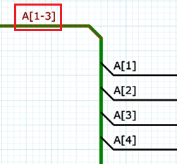
For a connected net, if you specify a label when one is not already assigned, then the net names that are listed in the Net/Bus command, Suggested labels box, are excluded from this check. They are also excluded if the specified label is contained within the existing name. For example, if you specify a label for the highlighted bus below, then:
For an unconnected net, specified net names are not excluded from this check. Note The Control column determines how the Net Label behaves when updated:
|
|
| Instance Net Label | Displays the instance net label associated with the net or bus. | |
| Line Width | Allows you to select the line width of the net or bus. To edit the line width values, right-click in this box and select Edit Line Width on the assist menu. The Line Width Tab dialog, Line Width tab is displayed | |
| Color | Click in the Value cell to display the Select color dialog. | |
| Net Type | Allows you to set the net or bus to one of the following options:
Note When forward annotating or migrating a schematic design, an error message is displayed if this value does not match the type of symbol it is connected to. For example, if a ground net is connected to power symbol in the design. |
|
|
Comment |
In the Comment dialog, you can associate a comment with the net or bus. You can specify a value over multiple lines. This dialog is launched when you point the cursor in this box, and then click the displayed |
|
| Clearance Class | Allows you to assign a clearance class to the selected signal. Point the cursor in the Clearance Class row to display the |
|
| SPICE OP Voltage | The Operating Point voltage for the selected net on the schematic sheet. This is simulated by the LTspice application. Operating Point voltage is used for analog simulation control units. Use it to set a voltage value to create adjusted results from calculations. | |
| Value | For the net or bus selected on the canvas, the values are listed that are associated with each property. |
When a pin is selected
| Item | Description | |
|---|---|---|
| Property | The properties are listed that are associated with the pin selected on the canvas. | |
| ID | The symbol pin number. You can map this value to a footprint reference pin number in the Part Editor Panel. | |
| Pin Number | The footprint reference pin number. You can map this value to a symbol pin number in the Part Editor Panel. | |
| Pin Label | The notation that is displayed for the mapping of the selected
pin.
|
|
| Pin Type | Displays the pin type of the selected item. The following values
may be displayed.
INPUT: the selected item is an input pin. OUTPUT: the selected item is an output pin. BIDIRECT: the selected item is a bidirectional pin. POWER: the selected item is a power pin. GROUND: the selected item is a ground pin. NC: the selected pin is not connected. UNDEFINED: the selected pin is not defined. |
|
| Coordinates | The X and Y coordinates of a pin that is selected on the canvas in Symbol Editor. These values are read-only. Click either "+" or "-" to toggle the display of the X and Y rows. The specified setting is saved until the application is restarted. | |
| Bit Count | Shows the number of bits associated with the pin. A bit count of more than one enables a single pin object to represent multiple pins. | |
| Implied Power Signal | In eCADSTAR Library Editor, this value is set in the Signal column for the pin. If the associated part is not instantiated into eCADSTAR Schematic Editor, then the value is allocated to the pin. If the part is instantiated into eCADSTAR Schematic Editor, then any signal that is connected to the pin will override this value. | |
| Pin Circuit Label | If implied power is specified for a part in eCADSTAR Library Editor, then the embedded signal is displayed that is associated with the relevant pin. This attribute is not available in eCADSTAR PCB Editor. | |
| Placement Group | Define the name of a placement group to associate the pin with it. The specified placement group is added to eCADSTAR PCB Editor when you forward annotate. Placement groups are used by the Gather Components command. | |
| Spice Pin Number | Allows you to specify the pin sequence order that is defined in the SPICE model. This can be specified in both the part library and the schematic. | |
| Value | For the pin selected on the canvas, the values are listed that are associated with each property. |
When a property viewer is selected
| Item | Description | |
|---|---|---|
| Property | The properties are listed that are associated with the property viewer that you select on the canvas. | |
| Coordinates | Displays the X and Y coordinates of the property viewer that is selected on the canvas in eCADSTAR Schematic Editor or Symbol Editor. These values are editable. Click either "+" or "-" to toggle the display of the X and Y rows. The specified setting is saved until the eCADSTAR application is restarted. | |
| Property Name | Displays the property definition. | |
| Value | If appropriate, you can specify the text that is displayed in the property viewer. | |
| Angle | Allows you to specify the angle at which the text is displayed. | |
| Origin | Allows you to specify the origin of the property viewer by selecting an item in the Origin box. The position of the property viewer is defined in relation to its origin. | |
| Font |
Allows you to specify the font of the property viewer. Select a font from the displayed values. To edit a displayed font, right-click in this box and select Edit Font on the assist menu. The Assignments dialog, Font tab is displayed. |
|
| Color <DEF> | Allows you to specify the color of the property viewer. Click in the Value cell to display the Select color dialog. | |
| Value | For the property viewer that is selected on the canvas, the values are listed that are associated with each property. |
When text is selected
| Item | Description | |
|---|---|---|
| Property | The properties are listed that are associated with the text selected on the canvas. | |
| Coordinates | Displays the X and Y coordinates of the specified text. These values are editable. Click either "+" or "-" to toggle the display of the X and Y rows. The specified setting is saved until the application is restarted. | |
| String | In the String dialog, you can specify the text string that is displayed, over multiple lines. This dialog is launched when you point the cursor in this box, and then click the displayed |
|
| Angle | Sets the angle at which the text is displayed. | |
| Origin | Allows you to specify the origin of the text by selecting an item in the Origin box. The position of the property viewer is defined in relation to its origin | |
| Font | Select a font from the displayed values. To edit a displayed font, right-click in this box and select Edit Font on the assist menu. The Assignments dialog, Font tab is displayed. | |
| Color | Click in the Value cell to display the Select color dialog. | |
| Value | For the text selected on the canvas, the values are listed
that are associated with each property. If you select variant text on the canvas, then Variant Text is shown in the Text row. You can edit the text value by pointing the cursor in the Value column, then clicking the |
When a figure is selected
| Item | Description | |
|---|---|---|
| Property | The properties are listed that are associated with the figure selected on the canvas. | |
| Line Width | Allows you to select the line width of the figure. To edit the line width values, right-click in this box and select Edit Line Width on the assist menu. The Line Width Tab dialog, Line Width tab is displayed. | |
| Line Type | Allows you to select the line type of the figure. To edit the line type values, right-click in this box and select Edit Line Type on the assist menu. The Line Type Tab dialog, Line Type tab is displayed. | |
| Color | Click in the Value cell to display the Select color dialog. | |
| Value | For the figure selected on the canvas, the values are listed that are associated with each property. |
When a circle is selected
| Item | Description | |
|---|---|---|
| Property | The properties are listed that are associated with the circle selected on the canvas. | |
| Line Width | Allows you to select the line width of the figure. To edit the line width values, right-click in this box and select Edit Line Width on the assist menu. The Line Width Tab dialog, Line Width tab is displayed. | |
| Line Type | Allows you to select the line type of the figure. To edit the line type values, right-click in this box and select Edit Line Type on the assist menu. The Line Type Tab dialog, Line Type tab is displayed. | |
| Radius | Displays the radius of the circle. | |
| Color | Click in the Value cell to display the Select color dialog. | |
| Value | For the circle selected on the canvas, the values are listed that are associated with each property. |
When a simulation frame is selected
| Item | Description | |
|---|---|---|
| Property | The properties are listed that are associated with the simulation frame selected on the eCADSTAR Schematic Editor canvas. | |
| Coordinates | Displays the X and Y coordinates of the selected simulation frame. These values are editable. Click either "+" or "-" to toggle the display of the X and Y rows. The specified setting is saved until the application is restarted. | |
| Angle | Specify the angle at which the selected simulation frame is displayed. | |
| Frame Type | Displays the frame type as simulation. | |
| Line Width | Allows you to select the line width of the figure. To edit the line width values, right-click in this box and select Edit Line Width on the assist menu. The Line Width Tab dialog, Line Width tab is displayed. | |
| Line Type | Allows you to select the line type of the figure. To edit the line type values, right-click in this box and select Edit Line Type on the assist menu. The Line Type Tab dialog, Line Type tab is displayed. | |
| Color | Specify the color of the selected simulation frame. Click in the Value cell to display the Select color dialog. | |
| Simulation Frame Name | Enter an alphanumeric value for the name of the simulation frame. | |
| Value | For the simulation frame that is selected on the canvas, the values are listed that are associated with each property. |
When a text frame is selected
| Item | Description | |
|---|---|---|
| Property | The properties are listed that are associated with the text frame selected on the eCADSTAR Schematic Editor canvas. | |
| Coordinates | Displays the X and Y coordinates of the selected text frame. These values are editable. Click either "+" or "-" to toggle the display of the X and Y rows. The specified setting is saved until the application is restarted. | |
| Angle | Specify the angle at which the selected text frame is displayed. | |
| Frame Type | Displays the frame type as text. | |
| Font | Select a font from the displayed values. To edit a displayed font, right-click in this box and select Edit Font on the assist menu. The Assignments dialog, Font tab is displayed. | |
| Text Color | Specify the color of the text in the frame. Click in the Value cell to display the Select color dialog. | |
| Line Width | Allows you to select the line width of the text frame. To edit the line width values, right-click in this box and select Edit Line Width on the assist menu. The Line Width Tab dialog, Line Width tab is displayed. | |
| Line Type | Allows you to select the line type of the text frame. To edit the line type values, right-click in this box and select Edit Line Type on the assist menu. The Line Type Tab dialog, Line Type tab is displayed. | |
| Frame Color | Specify the color of the selected text frame. Click in the Value cell to display the Select color dialog. | |
| File Name | Displays the path to the text file that you select in the Add Text Frame dialog, Text File Name box. | |
| Value | For the text frame that is selected on the canvas, the values are listed that are associated with each property. |
