
The Page Settings tab in the Plot dialog allows you to configure the pages that are plotted, including their contents, format and order. For each page, you can specify the objects, figures and layers that are included.
Page
The Page section allows you to create the pages that are plotted, and specify their order. Configure each page by selecting it in the Page table, selecting an item in the Page settings box and then specifying settings in the associated table.
| Item | Description |
|---|---|
| Page name | Shows the name of the page.
|

|
Moves a selected page to the top of the list. Select multiple pages using the Ctrl or Shift key. |

|
Moves a selected page up by one position. Select multiple pages using the Ctrl or Shift key. |

|
Moves a selected page down by one position. Select multiple pages using the Ctrl or Shift key. |

|
Moves a selected page to the bottom of the list. Select multiple pages using the Ctrl or Shift key. |
| Add | Inserts a new page below the currently-selected page in the Page box. |
| Delete | Deletes the page that you select in the Page box. Multiple pages can be deleted by selecting them using the Ctrl or Shift key and clicking Delete. |
| Add Layer View | Displays the Add Page for Layer View dialog. From this dialog, you can select a layer from the current layer set to be added to the Page table as a new page. It is inserted below the currently-selected page in the Page box. Multiple layers can be selected using the Ctrl or Shift key. |
| Duplicate | Duplicates a page and inserts it below the currently-selected page in the Page box. |
Assist menu
The following menu items are displayed by right-clicking in the Page box.
| Item | Description |
|---|---|
| Undo | Selecting this option undoes the last action. |
| Redo | Selecting this option redoes the last undone action. |
| Resize to Text | Selecting this option resizes the grid to accommodate the longest text field. |
| Resize Grid | Applies the default widths to the columns in the table. |
| Insert Page Below | Selecting this option performs the same function as clicking the Add button as described above. |
| Delete Page | Selecting this option performs the same function as clicking the Delete button as described above. |
| Duplicate Page | Selecting this option performs the same function as clicking the Duplicate button as described above. |
| Add Page for Layer View | Displays the Add Page for Layer View dialog. From this dialog, you can select a page from the current Layer Set to be added. It is inserted it below the currently-selected page in the Page box. |
| Copy Entire Table | Selecting this option copies the entire panel table to the clipboard. |
Page settings
Layer to output
| Item | Description | |
|---|---|---|
| View filter |
|
|
| Layer type |
|
|
| Output target |
|
|

|
Specify whether to display board layers. | |

|
Specify whether to display conductor layers. | |

|
Specify whether to display dielectric layers. | |
|
Specify whether to display non-conductor layers. | |
|
Specify whether to display keepout layers related to a conductor layer and other layers (with layer types of Component keepout, Track & Via keepout, Only via keepout, Only track keepout, Only via hole keepout, and Others). | |

|
Specify whether to display user-defined layers. | |
|
|
Moves a selected page to the top of the Layer to output table. Select multiple pages using the Ctrl or Shift key. | |
|
|
Moves a selected page up by one position in the Layer to output table. Select multiple pages using the Ctrl or Shift key. | |
|
|
Moves a selected page down by one position in the Layer to output table. Select multiple pages using the Ctrl or Shift key. | |
|
|
Moves a selected page to the bottom of the Layer to output table. Select multiple pages using the Ctrl or Shift key. |
A track keepout area restricts the use of any surface mount conductor object. This includes the following objects.
- Pad/Padstacks
- Route/Line
- Area
- Text
The only conductor objects that are not considered are plated through holes (vias or padstacks). You can configure track keepout areas in the Net Keepout Settings dialog. This allows you to specify the nets that are permitted in the relevant area.
Layer to output Table
Specify output layers and attributes for layers. If a hole is specified, then round holes, slot holes and holes in padstacks are plotted.
| Item | Description | |
|---|---|---|
| Layer name | Displays the layer name. | |
| Output | If selected, the associated layer is set as an output target. If a hole is selected as the output target, round holes, slot holes and holes in padstacks are plotted. | |
| Mode | No width | Layers are plotted with no width. |
| Width | Layers are plotted with width. | |
| Fill without outline | Layers are filled. | |
| Fill with outline | Layers are filled. Object outlines are also plotted. | |
| Pen width | Real number between 0.0 and 2000.0 mm | Specify the line width. |
| Pen color | Specify the line color that is used to plot layer objects. This can be specified when Set color for pen and pallet separately is selected in the Options dialog. | |
| Pallet color | Specify the line color that is used to plot layer objects. This can be specified when Set color for pen and pallet separately is selected in the Options dialog. | |
| Transparency | Specify the transparency that is applied when PDF
is selected in the Basic
Settings Tab, Output box, and
Fill without outline or Fill with outline is selected in the
Mode box in this table. Specify
an integer between 0 and 100.
|
|
| Mirror | Off | Layers are not flipped (mirrored). |
| X-axis | Layers are flipped (mirrored) in the X direction. | |
| Y-axis | Layers are flipped (mirrored) in the Y direction. | |
| X without text | All objects except text are flipped (mirrored) in the X direction. | |
| Y without text | All objects except text are flipped (mirrored) in the Y direction. | |
| X only text | Only text is flipped (mirrored) in the X direction. | |
| Y only text | Only text is flipped (mirrored) in the Y direction. | |
| Positive/Negative | This column is made available if you select Positive/Negative in the Technology Editor dialog, Layer attribute column. It allows you to specify whether both positive data and negative data is plotted, or whether only positive data or only negative data is plotted. | |
| Positive/Negative | Both positive data and negative data is plotted.
|
|
| Positive | Only positive data is plotted. Data is plotted as positive (filled) objects. | |
| Negative | Only negative data is plotted. Data is plotted as positive
(filled) objects. The following items are negative data:
|
|
Object Table
Specify output targets and attributes by object type.
| Item | Description | |
|---|---|---|
| Object | Displays the object name. | |
| Output | If selected, the associated object is set as an output target. | |
| Valid | Allows you to specify whether the values that are plotted for
a particular attribute are the values specified in this tab, or
the values that are set by the relevant design rule.
|
|
| Mode | No width | Objects are plotted with no width. |
| Width | Objects are plotted with width. | |
| Fill without outline | Objects are filled. | |
| Fill with outline | Objects are filled. Object outlines are also plotted. | |
| Pen width | Real number between 0.0 and 2000.0 mm | Specify the line width. |
| Pen color | Specify the line color that is used to plot objects. This can be specified when Set color for pen and pallet separately is selected in the Options dialog. | |
| Pallet color | Specify the line color that is used to plot objects. This can be specified when Set color for pen and pallet separately is selected in the Options dialog. | |
Component Table
Specify output targets and attributes for components.
| Item | Description | |
|---|---|---|
| Output all | Allows you to specify whether all displayed components are plotted, regardless of whether the Output check box is selected for them.
Note If you click Export parameters, then this setting is saved to the exported parameter file. It is applied when the parameter file is loaded in the Plot dialog. |
|
| Reference designator filter | Components are displayed in the Component table whose name partially matches the value that you enter in this box. | |
| Component | Displays the component name. Attributes for terminals are specified in a separate table at the bottom of the dialog. | |
| Output | If selected, then the associated component is set as an output target. Note To output all displayed components, select Output all. The Output column is hidden. However, individual settings in this column are not changed. |
|
| Valid | Allows you to specify whether the values that are plotted for
a particular attribute are the values specified in this tab, or
the values that are set by the relevant design rule.
|
|
| Mode | No width | Components are plotted with no width. |
| Width | Components are plotted with width. | |
| Fill without outline | Components are filled. | |
| Fill with outline | Components are filled. Object outlines are also plotted. | |
| Pen width | Real number between 0.0 and 2000.0 mm | Specify the line width. |
| Pen color | Specify the line color that is used to plot objects in a component. This can be specified when Set color for pen and pallet separately is selected in the Options dialog. | |
| Pallet color | Specify the line color that is used to plot objects in a component. This can be specified when Set color for pen and pallet separately is selected in the Options dialog. | |
Net Table
Specify output targets and attributes for nets.
| Item | Description | |
|---|---|---|
| Output all | Allows you to specify whether all displayed nets are plotted, regardless of whether the Output check box is selected for them.
Note If you click Export parameters, then this setting is saved to the exported parameter file. It is applied when the parameter file is loaded in the Plot dialog. |
|
| Net name filter | Nets are displayed in the Net table whose name partially matches the value that you enter in this box. | |
 Power/Ground Power/Ground
|
|
|
| Net name | Displays the net name | |
| Output | If selected, then the associated net is set as an output target. Note To output all displayed nets, select Output all. The Output column is hidden. However, individual settings in this column are not changed. |
|
| Valid | Allows you to specify whether the values that are plotted for
a particular attribute are the values specified in this tab, or
the values that are set by the relevant design rule.
|
|
| Mode | No width | Nets are plotted with no width. |
| Width | Nets are plotted with width. | |
| Fill without outline | Nets are filled. | |
| Fill with outline | Nets are filled. Object outlines are also plotted | |
| Pen width | Real number between 0.0 and 2000.0 mm | Specify the line width. |
| Pen color | Specify the line color that is used to plot net objects. This can be specified when Set color for pen and pallet separately is selected in the Options dialog. | |
| Pallet color | Specify the line color that is used to plot net objects. This can be specified when Set color for pen and pallet separately is selected in the Options dialog. |
Hole (From-To)
Specify output targets and attributes in From-To of holes. Valid settings for round holes, slot holes, padstack holes, and non-circular holes.
| Item | Description | |
|---|---|---|
| From-To | Displays the From-To name. | |
| Output | If selected, the associated hole is set as an output target. | |
| Valid | Allows you to specify whether the values that are plotted for
a particular attribute are the values specified in this tab, or
the values that are set by the relevant design rule.
|
|
| Mode | No width | Holes are plotted with no width. |
| Width | Holes are plotted with width. | |
| Fill without outline | Holes are filled. | |
| Fill with outline | Holes are filled. object outlines are also plotted. | |
| Pen width | Real number between 0.0 and 2000.0 mm | Specify the line width. |
| Pen color | Specify the line color that is used to plot holes. This can be specified when Set color for pen and palette separately is selected in the Options dialog. | |
| Palette color | Specify the line color that is used to plot holes. This can be specified when Set color for pen and palette separately is selected in the Options dialog. | |
Round holes and non-circular holes are treated as through holes.
Plating
Specify output targets and attributes on Plated holes. Valid settings for objects of round holes, slot holes, padstack holes, and non-circular holes.
| Item | Description | |
|---|---|---|
| Plating | Displays the Plated or Non plated attribute name. | |
| Output | If selected, the associated hole is set as an output target. | |
| Valid | Allows you to specify whether the values that are plotted for
a particular attribute are the values specified in this tab, or
the values that are set by the relevant design rule.
|
|
| Mode | No width | Holes are plotted with no width. |
| Width | Holes are plotted with width. | |
| Fill without outline | Holes are filled. | |
| Fill with outline | Holes are filled. Object outlines are also plotted. | |
| Pen width | Real number between 0.0 and 2000.0 mm | Specify the line width. |
| Pen color | Specify the line color that is used to plot holes. This can be specified when Set color for pen and pallet separately is selected in the Options dialog. | |
| Pallet color | Specify the line color that is used to plot holes. This can be specified when Set color for pen and pallet separately is selected in the Options dialog. | |
Round holes, and non-circular holes are treated as non plated holes.
Hole Diameter
Specify output targets and attributes on Hole diameter/Hole type of holes. Non-circular holes do not have hole diameters and hole types and thus do not refer to this setting.
| Item | Description | |
|---|---|---|
| Hole diameter | Displays the hole diameter. | |
| Hole type | Displays the hole type. | |
| Output | If selected, the associated hole is set as an output target. | |
| Valid | Allows you to specify whether the values that are plotted for
a particular attribute are the values specified in this tab, or
the values that are set by the relevant design rule.
|
|
| Mode | No width | The hole is plotted with no width. |
| Width | The hole is plotted with width. | |
| Fill without outline | The hole is filled. | |
| Fill with outline | The hole is filled. Object outlines are also plotted. | |
| Pen width | Real number between 0.0 and 2000.0 mm | Specify the line width. |
| Pen color | Specify the line color that is used to plot the hole. This can be specified when Set color for pen and pallet separately is selected in the Options dialog. | |
| Pallet color | Specify the line color that is used to plot the hole. This can be specified when Set color for pen and pallet separately is selected in the Options dialog. | |
Additional output
Specify settings of additional information output, such as reference designators, pin numbers and pin names.
| Item | Description | |
|---|---|---|
| Reference designator | If selected, the Reference designator check box is made available for all components. The fields in the Reference designator section are made available. | |
| Pin number/name | If selected, the Pin number/name check box is made available for all components. The fields in the Pin number/name section are made available. | |
| Side A | If selected, the Reference Designator and Pin number/name check boxes can be set for components on side A. | |
| Side B | If selected, the Reference Designator and Pin number/name check boxes can be set for components on side B. | |
| Both | If selected, the Reference Designator and Pin number/name check boxes can be set for components on both sides of the board. | |
| Component | Shows the name of the component. | |
| Reference designator | If selected, reference designators are plotted for the associated component. | |
| Pin number/name | If selected, pin numbers and names are plotted for the associated component. |
Reference designator
Specify parameters for exporting the reference designator as a string. This section is made available when Reference designator is selected in the Additional info. to output section.
| Item | Description | |||||||||||||||||||||
|---|---|---|---|---|---|---|---|---|---|---|---|---|---|---|---|---|---|---|---|---|---|---|
| Attributes | ||||||||||||||||||||||
| Mode | No width | Reference designators are plotted with no width. | ||||||||||||||||||||
| Width | Reference designators are plotted with width. | |||||||||||||||||||||
| Fill without outline | Reference designators are filled. | |||||||||||||||||||||
| Fill with outline | Reference designators are filled. Object outlines are also plotted. | |||||||||||||||||||||
| Pen width | Real number between 0.0 and 2000.0 mm | Specify the line width. | ||||||||||||||||||||
| Text color | Specify the text color for exporting reference designators. | |||||||||||||||||||||
| Variant component | Allows you to specify whether the reference designators are plotted for variant components in the design. | |||||||||||||||||||||
| Variant component | If the design contains variant components, then the reference designators are plotted for them. For variant components, an underscore and a number are added to its reference designator. For example, a variant of component "C2" is displayed in eCADSTAR PCB Editor as "C2_1". If you specify a suffix of “VAR”, for example, then the reference designator for the variant version would be displayed “C2_VAR1”. | |||||||||||||||||||||
| Master component | The reference designators are only plotted for master components in the design. | |||||||||||||||||||||
| Character Attributes settings | This section allows you to specify the attributes of the text that is used for the reference designators that are plotted. | |||||||||||||||||||||
| Font | Specify the font that is used for text data. If you select
the zafont0, _zafont0,
zpafont0 or _zpafont0
font, then the following symbols are displayed for the associated
character.
|
|||||||||||||||||||||
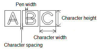
| Character width | Specify the character width as a real number between 0.0 and 2000.0 mm. If 0.0 is set, then the character width is automatically calculated based on the board outline and the size of the layout area. You can also set it from Select font sizes, in this dialog. This value refers to the dimensions of the non-displayed box which contains the character, rather than the actual width of the character. | |||||||||||||||||||||
| Character height | Specify the character height as a real number between 0.0 and 2000.0 mm. If 0.0 is set, the character height is automatically calculated based on the board outline and the size of the layout area. You can also set it from Select font sizes, in this dialog. This value refers to the dimensions of the non-displayed box which contains the character, rather than the actual height of the character. | |||||||||||||||||||||
| Character spacing | Specify the spacing between characters as a real number between 0.0 and 2000.0 mm. You can also set it from Select font sizes, in this dialog. This value refers to the spacing between the non-displayed boxes which contain the characters, rather than the actual spacing between characters. | |||||||||||||||||||||
| Pen width | Specify the pen width of text as a real number between 0.0 and 2000.0 mm. You can also set it from Select font sizes, in this dialog. Because of the method used by eCADSTAR to place text on the canvas, the values that you specify do not refer to the units in the design. | |||||||||||||||||||||
| Select font sizes | Click Select to display the Font setting Dialog. This contains the text size and spacing criteria that you define for eCADSTAR PCB Editor or Footprint Editor. Select a row in the dialog, and click Apply or OK to apply the settings to the Plot dialog. Existing values in the Plot dialog are overwritten by the values that you specify. | |||||||||||||||||||||
| Coordinates settings | Allows you to specify the position and angle of the reference designators that are plotted | |||||||||||||||||||||
| Coordinates | Bottom-Left |
|
||||||||||||||||||||
| Middle-Left |
|
|||||||||||||||||||||
| Top-Left |
|
|||||||||||||||||||||
| Bottom-Center |
|
|||||||||||||||||||||
| Middle-Center |
|
|||||||||||||||||||||
| Top-Center |
|
|||||||||||||||||||||
| Bottom-Right |
|
|||||||||||||||||||||
| Middle-Right |
|
|||||||||||||||||||||
| Top-Right |
|
|||||||||||||||||||||
| Adjust position | X-axis | Specify the offset (relative travel distance) in the X direction from the position specified in "Coordinates" (real number between -5000.0 and 5000.0 mm). | ||||||||||||||||||||
| Y-axis | Specify the offset (relative travel distance) in the Y direction from the position specified in "Coordinates" (real number between -5000.0 and 5000.0 mm). | |||||||||||||||||||||
| Plot angle | Specified angle | Pin numbers (or pin names) are output at the angle specified in Angle. | ||||||||||||||||||||
| Component angle | Pin numbers (or pin names) are output at the angle of component. | |||||||||||||||||||||
| Calc. from rect. of comp. | The orientation ("landscape" or "portrait") is determined based on the width and height of the circumscribed rectangle of a component. For "portrait", the view is rotated 90 degrees counterclockwise. | |||||||||||||||||||||
| Angle | Specify the angle at which to plot text with Angle set to Specified angle (real number greater than or equal to 0.0 but less than 360). | |||||||||||||||||||||
| Mirror | Off | Reference designators are not flipped (mirrored). | ||||||||||||||||||||
| X-axis | Reference designators are flipped (mirrored) in the X direction. | |||||||||||||||||||||
| Y-axis | Reference designators are flipped (mirrored) in the Y direction. |
- A license is required to access the variation functionality in eCADSTAR.
- When you add text in eCADSTAR,
each character is placed within a box, which is not displayed. The
values that you specify in the above section refer to the dimensions
of this box, rather than the dimensions of the characters. The actual
dimensions of characters will vary, depending on their position within
this box. This is illustrated in the following image.
Pin number/name
Specify parameters for exporting pin numbers or pin names as a string. This section is made available when Pin number/name is selected in the Additional info. to output section.
| Item | Description | |||||||||||||||
|---|---|---|---|---|---|---|---|---|---|---|---|---|---|---|---|---|
| Output attributes | Pin number | Pin numbers are plotted as text. | ||||||||||||||
| Pin name | Pin names are plotted as text. | |||||||||||||||
| Pin number + Pin name | "Pin numbers (pin names)" are plotted as text. | |||||||||||||||
| Mode | No width | Pin numbers (or pin names) are plotted with no width. | ||||||||||||||
| Width | Pin numbers (or pin names) are plotted with width. | |||||||||||||||
| Fill without outline | Pin numbers (or pin names) are filled. | |||||||||||||||
| Fill with outline | Pin numbers (or pin names) are filled. Object outlines are also plotted. | |||||||||||||||
| Pen width | Real number between 0.0 and 2000.0 mm | Specify the line width. | ||||||||||||||
| Text color | Specify the text color for exporting pin numbers or pin names. | |||||||||||||||
| Character Attributes settings | This section allows you to specify the attributes of the text that is used for the pin numbers or pin names that are plotted. | |||||||||||||||
| Font | Specify the font that is used for text data. If you select
the zafont0, _zafont0,
zpafont0 or _zpafont0
font, then the following symbols are displayed for the associated
character.
|
|||||||||||||||
| Character width | Specify the character width as a real number between 0.0 and 2000.0 mm. If 0.0 is set, the character width is automatically calculated based on the board outline and the size of the layout area. You can also set it from Select font sizes, in this dialog. | |||||||||||||||
| Character height | Specify the character height as a real number between 0.0 and 2000.0 mm. If 0.0 is set, the character height is automatically calculated based on the board outline and the size of the layout area. You can also set it from Select font sizes, in this dialog. | |||||||||||||||
| Character spacing | Specify the character height as a real number between 0.0 and 2000.0 mm. You can also set it from Select font sizes, in this dialog. | |||||||||||||||
| Pen width | Specify the pen width of text as a real number between 0.0 and 2000.0 mm. You can also set it from Select font sizes, in this dialog. | |||||||||||||||
| Select font sizes | Displays the Font setting Dialog. This dialog allows you to set the character width, height and spacing by selecting the appropriate row. | |||||||||||||||
| Coordinates settings | Allows you to specify the position and angle of the pin numbers or pin names that are plotted. | |||||||||||||||
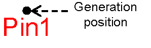
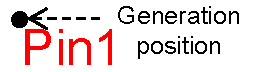
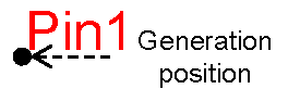
| Generation position | Terminal ref. point | Pin numbers or pin names are plotted at terminal reference
points. |
||||||||||||||
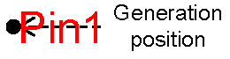
| Center of terminal | Text data is output to the center point for each object that
comprises terminals. |
|||||||||||||||
| Coordinates | Bottom-Left |

|
||||||||||||||
| Middle-Left |

|
|||||||||||||||
| Top-Left |

|
|||||||||||||||
| Bottom-Center |
|
|||||||||||||||
| Middle-Center |

|
|||||||||||||||
| Top-Center |

|
|||||||||||||||
| Bottom-Right |
|
|||||||||||||||
| Middle-Right |
|
|||||||||||||||
| Top-Right |
|
|||||||||||||||
| Adjust position | X-axis | Specify the offset (relative travel distance) in the X direction from the position specified in "Coordinates" (real number between -5000.0 and 5000.0 mm). | ||||||||||||||
| Y-axis | Specify the offset (relative travel distance) in the Y direction from the position specified in "Coordinates" (real number between -5000.0 and 5000.0 mm). | |||||||||||||||
| Plot angle | Specified angle | Pin numbers or pin names are output at the angle specified in the Angle field. | ||||||||||||||
| Component angle | Pin numbers or pin names are output at the angle of the component. | |||||||||||||||
| Calc. from rect. of comp. | The orientation ("landscape" or "portrait") is determined based on the width and height of the circumscribed rectangle of the component. For "portrait", the view is rotated 90 degrees counterclockwise. | |||||||||||||||
| Calc. from rect. of term. | The orientation ("landscape" or "portrait") is determined based on the width and height of the circumscribed rectangle of the pin. For "portrait", the view is rotated 90 degrees counterclockwise. | |||||||||||||||
| Angle | Specify the angle at which to plot text with Angle set to Specified angle (real number greater than or equal to 0.0 but less than 360). | |||||||||||||||
| Mirror | Off | Pin numbers or pin names are not flipped (mirrored). | ||||||||||||||
| X-axis | Pin numbers r pin names are flipped (mirrored) in the X direction. | |||||||||||||||
| Y-axis | Pin numbers or pin names are flipped (mirrored) in the Y direction. |
General
Specify parameters for exporting pin numbers or pin names as a string.
| Value | Description | |
|---|---|---|
| Output only component | If selected, only objects in components are plotted. | |
| Narrow down to only terminal | If selected, only objects in terminals are plotted. | |
| Variation | Allows you to specify whether data is plotted for the whole design, or only for the variant components that you specify. | |
| Variant |
|
- A license is required to access variation functionality in eCADSTAR.
- If Set color for pen and pallet separately is selected in the Options dialog, then both Pen color and Pallet color are displayed and can be set independently. Otherwise the Color column is displayed. This column enables you to specify the same color for both the pen and pallet.
