
The Basic Settings tab in the Plot Dialog allows you to specify the format of the design data that is exported, and the pages that are included. The fields that are displayed in the Output section are dependent on the format specified in the Output section.
Output
Specify the destination for the exported design data. You can either specify one of the following formats, or select an available printer. Data can either be sent to a selected application or device, or exported to files.
| Item | Description | |
|---|---|---|
Allows you to export design data as either multiple PDF files,
or as a single PDF file. This provides an advantage over the Microsoft Print to PDF option, which
cannot output design data as a single PDF file. Design objects
are exported as individual objects within the PDF file, rather
than as a flat image, as produced by the other available options.
You can then interact with these objects by highlighting, copying
and annotating them, for example. Bookmarks can also be added
to the exported data to help navigation, including references
for component data.
|
||
| Output each page | The pages that you select in the Pages
section in this tab are exported as individual PDF files. If you
select this option, specify the folder to which the files are
exported by clicking  by the Output folder box.
 |
|
| Output all to one file | The pages that you select in the Pages
section in this tab are exported as a single PDF file. If you
select this option, specify the name of the file by clicking by the Output file box. |
|
| Output folder | Shows the folder to which the selected pages are exported.
This is specified by clicking the associated
button. This box is made unavailable if Output
all to one file is selected. |
|
|
|
In the Select Folder dialog, specify the folder to which the selected pages are exported. This button is made unavailable if Output all to one file is selected. | |
| Output file | Shows the name of the PDF file that is exported. This is specified
by clicking the associated
button. This button is made unavailable if Output
each page is selected. |
|
|
|
Select a file in the Save As dialog. | |
| Create bookmarks for components |
If selected, references for component data are created, and are exported as PDF bookmarks. |
|
| Compress | If selected, the size of PDF files that are exported is reduced. | |
| Use transparency | If selected, the transparency settings of any images are taken into account. | |
| Vector format | Outputs the design data in vector format (.plv). A file is created for each page specified in the Page section, in the Page Settings Tab. | |
| Output folder | Shows the folder to which the selected pages are exported.
This is specified by clicking the associated
button. |
|
|
|
In the Select Folder dialog, specify the folder to which the selected pages are exported. | |
| Send to OneNote 2016 | Outputs the design data in Microsoft OneNote format. Microsoft OneNote is used for free-form information gathering, and allows you to share content with other OneNote users. | |
| Output to file | Allows you to additionally export the design data to a specified
file.
|
|
| Output folder | Shows the folder to which the selected pages are exported.
This is specified by clicking the associated
button. |
|
|
|
In the Select Folder dialog, specify the folder to which the selected pages are exported. | |
| Microsoft XPS Document Writer | Outputs the design data in Microsoft XPS Document Writer format. Microsoft XPS Document Writer allows you to create XML Paper Specification (XPS) document files. | |
| Output to file | Allows you to either export the design data as an OpenXPS Document
(.oxps) file, or export it as multiple
files that do not have a file extension.
|
|
| Output folder | Shows the folder to which the selected pages are exported.
This is specified by clicking the associated
button. |
|
|
|
In the Select Folder dialog, specify the folder to which the selected pages are exported. | |
| Microsoft Print to PDF | Outputs the design data using the "Microsoft Print to PDF" function. This is a native PDF printer, which does not allow you to create PDF bookmarks, or to export multiple pages to a single PDF file. If more advanced PDF settings are required, then select the PDF option. | |
| Output to file | Allows you to either export the design data as a PDF file,
or export it as multiple files with no file extension.
|
|
| Output folder | Shows the folder to which the selected pages are exported.
This is specified by clicking the associated
button. |
|
|
|
In the Select Folder dialog, specify the folder to which the selected pages are exported. | |
| <Printer name> | Allows you to either send the design data to the specified printer, or export it as multiple files. | |
| Output to file | Allows you to specify whether the design data is sent to a
specified printer, or exported as files.
|
|
| Output folder | Shows the folder to which the selected pages are exported. | |
|
|
In the Select Folder dialog, specify the folder to which the selected pages are exported. |
Paper
Set the size and orientation of the exported data, and specify the margins.
| Value | Description | |
|---|---|---|
| Size | ||
| A0 to A4 | Select an available format for the exported data by selecting it in the Size box. | |
| JIS B1 to JIS B5 | Select an available format for the exported data by selecting it in the Size box. | |
| ANSI A to ANSI E | Select an available format for the exported data by selecting it in the Size box. | |
| Custom size | If selected, the Width and Height fields are made available. These allow you to set the width and height of the exported data. | |
| Auto | Automatically selects an appropriate format. If an appropriate format is not found, the width and height of the exported data is used. | |
| Width | Set the width of the exported data (real number between 0.001 and 5000.0 mm). This field is only available when Custom size is selected in the Size field. | |
| Height | Set the height of the exported data (real number between 0.001 and 5000.0 mm). This field is only available when Custom size is selected in the Size field. | |
| Orientation | Set the orientation of the exported data, or select Auto to set the orientation automatically. | |
| Landscape | Design data is exported in landscape format using the specified paper size. | |
| Portrait | Design data is exported in portrait format using the specified paper size. | |
| Auto | Exported data is oriented automatically, as follows:
|
|
| Margin | Set the margins for the exported data. | |
| Top | Specify the top margin for the exported data (real number between 0.0 and 5000.0 mm). | |
| Bottom | Specify the bottom margin for the exported data (real number between 0.0 and 5000.0 mm). | |
| Left | Specify the left margin for the exported data (real number between 0.0 and 5000.0 mm). | |
| Right | Specify the right margin for the exported data (real number between 0.0 and 5000.0 mm). This setting is valid when Auto of Scale is set to ON, or Auto of Adjust position is set to ON. |
Coordinates settings
Specify the area on the canvas that is exported. You can also rotate the exported data, and change its size and position.
| Value | Description | |
|---|---|---|
| Specify plot area | ||
| Selected | Allows you to define a rectangular output area by specifying the coordinates of its start and end points. The fields in this section are made available. Design data is exported that is only in the area defined by the start and end points that you specify. | |
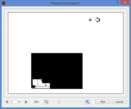
| Not-selected | All of the design data in the PCB is exported. The fields in
this section are made unavailable. This is illustrated in the
following image of the Preview
dialog.
|
|
| Start point | Specify the X and Y coordinates of the start point of a rectangular area. | |
| X | Specify the X coordinates of the start point (real number between -5000.0 and 5000.0 mm). | |
| Y | Specify the Y coordinates of the start point (real number between -5000.0 and 5000.0 mm). | |
| End point | Specify the X and Y coordinates of the end point of a rectangular area. | |
| X | Specify the X coordinates of the end point (real number between -5000.0 and 5000.0 mm). | |
| Y | Specify the Y coordinates of the end point (real number between -5000.0 and 5000.0 mm). | |
| Rotate | Specify the angle of rotation for the exported data. | |
| 0-degree (No rotation) | The exported data is not rotated. | |
| 90-degree | The exported data is rotated counterclockwise by 90 degrees. | |
| 180-degree | The exported data is rotated counterclockwise by 180 degrees. | |
| 270-degree | The exported data is rotated counterclockwise by 270 degrees. | |
| Scale | Allows you to increase the size of the exported data. | |
| Auto | Automatically scales the exported data to fit the size specified in the Paper section (excluding margins). | |
| Factor | Specify a real number between 0.02 and 50.0. The exported data is scaled using the specified value. | |
| Adjust position | Allows you to change the position of the exported data. | |
| Auto |
|
|
| X-axis | Specify the distance in the X direction that the exported data is offset by (real number between -5000.0 and 5000.0 mm). | |
| Y-axis | Specify the distance in the Y direction that the exported data is offset by (real number between -5000.0 and 5000.0 mm). |
Pages
Specify the pages that are exported.
| Value | Description |
|---|---|
| Output | If selected, the associated page is exported. |
| Page name | Shows the name of the page that is specified in the Page Settings tab. |

|
Moves a selected page to the top of the list. Select multiple pages using the Ctrl and Shift keys. |

|
Moves a selected page up by one position. Select multiple pages using the Ctrl and Shift keys. |

|
Moves a selected page down by one position. Select multiple pages using the Ctrl and Shift keys. |

|
Moves a selected page to the bottom of the list. Select multiple pages using the Ctrl and Shift keys. |
