
The Canvas View Settings
dialog allows you to set whether to show an object, the color, the units
for numerical values and the number of digits to display. Any settings
that are made in the dialog are applied immediately on the canvas. Display
this dialog by clicking View > Canvas
>  Canvas View Settings on the Footprint Editor ribbon.
Information
Attributes
Select whether to show the attributes of pins, areas etc.
| Setting | Description | |
|---|---|---|
| Item | Value | |
| Pin number | Selected | Pin numbers are displayed (except in 3D view mode). |
| Not selected | Pin numbers are hidden. | |
| Reference point of pin | Selected | The reference points of pins are displayed on the footprint. |
| Not selected | The reference points of pins are hidden on the footprint. | |
| Reference point of padstack | Selected | Displays the reference point of the padstack on the footprint in 2D View mode. This can be used as a guide when positioning the padstack in relation to other objects on the footprint. Set the color of the reference point in the Application Settings dialog, Reference point of padstack section. |
| Not selected | The reference point of the padstack is not displayed on the footprint. | |
| Attributes | Selected | Data attributes (the heights of component areas displayed on the canvas) are displayed. They are not displayed in 3D view mode. |
| Not selected | Data attributes are hidden. | |
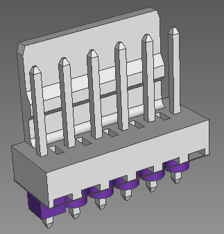
3D Model
Allows you to configure the display of 3D models in the 2D view and 3D view modes.
| Setting | Description | |
|---|---|---|
| Transparency | If you select Wireframe
or Fill in the 2D
view or 3D view section,
then this setting allows you to display 3D models transparently.
This makes the background visible through them.
This feature is illustrated below for the 3D view mode.
|
|
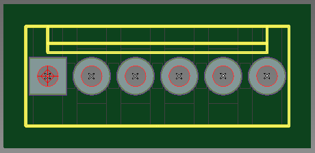
| 2D view | Allows you to configure the display of 3D models when viewing the board in 2D view mode. To make the 3D models more visible, turn off the top placement and bottom placement layers. This is done by deselecting Visible layer in the Layer Settings Panel for these layers. | |
| Off | 3D models are not displayed in 2D view mode. | |
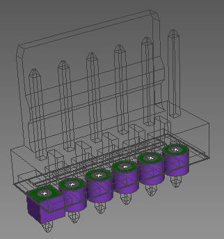
| Wireframe |
Only the lines and vertices of the 3D model are displayed. This is illustrated below.
|
|
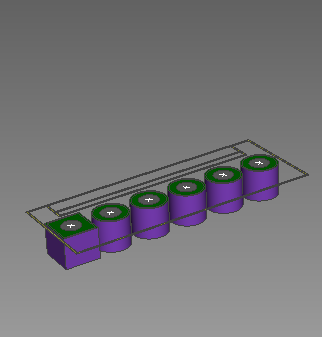
| Fill | The areas are filled between the lines and vertices of
the 3D model. This is illustrated below.
|
|
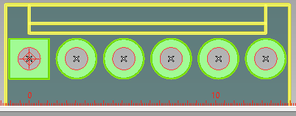
| 3D view | Off | 3D models are not displayed on the canvas in 3D
view mode. This is illustrated below.
|
| Wireframe | Only the lines and vertices of the 3D model are displayed.
This is illustrated below.
|
|
| Fill | The areas are filled between the lines and vertices of
the 3D model. These areas are shaded, depending on the angle of
view. This is illustrated below.
|
|
Unit/Background
Units
Allows you to temporarily change the units of measurements, and the number of decimal places to display for the footprint. Alternatively, specify these settings in the Unit and Decimal boxes on the status bar in Footprint Editor.
| Setting | Description | |
|---|---|---|
| Item | Value | |
| Units | For the footprint that is displayed on the canvas, this section
allows you to temporarily change the units for measurements.
Note This value is not saved when you close the footprint. When you reopen the footprint, the value is used that is specified in eCADSTAR Library Editor. This is set in the Unit box on the status bar in eCADSTAR Library Editor. |
|
| mm | Numeric values are displayed in mm. | |
| inch | Numeric values are displayed in inches. | |
| Micron | Numeric values are displayed in microns. | |
| mil | Numeric values are displayed in mil (1 mil = 1 thousandth of an inch). | |
| Decimal places | For the footprint that is displayed on the canvas, this section
allows you to temporarily change the number of decimal places
for numeric values. Alternatively, specify this value in
the Decimal places box on the status bar. Select a value between 0 and 5.
Note This value is not saved when you close the footprint. When you reopen the footprint, the value is used that is specified in eCADSTAR Library Editor. This is set in the Decimal places box on the status bar in eCADSTAR Library Editor. |
|
Background
Allows you to specify the color of the drawing area background, and the color of the grid and ruler.
| Setting | Description | |
|---|---|---|
| Item | Value | |
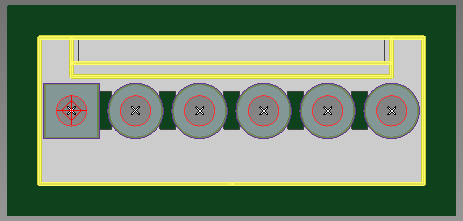
| Fill drawing area background | Selected | In 2D view mode, the drawing area background of the displayed footprint is displayed, and filled in the color specified in the Select color dialog. The Color button is made available. Click the Color button to select a color in the displayed dialog. This setting is not saved when you save the footprint. |
| Not selected | The drawing area background is not displayed. | |
| Color | Displays the Select color dialog. In the Select color dialog, specify a color and click OK. The drawing area background of the displayed footprint is filled in the selected color. | |
| Grid color | For the displayed footprint, this setting allows you to temporarily
specify the color of the grid on the canvas. This setting is not
saved when the footprint is saved. Click the Grid
color button to display
the Select color dialog. In the
Select color dialog, specify a
color and click OK.
Note
|
|
| Ruler color |
For the displayed footprint, this setting allows you to temporarily specify the color of the ruler that is displayed on the X and Y axes of the canvas. This setting is not saved when the footprint is saved. Click the Ruler color button to display the Select color dialog. In the Select color dialog, specify a color and click OK. The ruler is shown below for the X axis of the canvas.
|
|
To update the library with the Grid color and Ruler color settings that you specify, click Design > Export > Footprint Colors on the Footprint Editor ribbon. This saves these settings, as well as the color settings specified in the Layer Settings Panel. Any footprint that you open from the library will use the exported settings.
