
The Detail tab in the Part Editor panel allows you to configure a selected part. You can specify its type and class, and its associated footprint, symbol and pin assignment. It is displayed by selecting a part in the eCADSTAR Library Editor and clicking Home > Edit > Part on the ribbon. In the Part Editor panel, select the Detail tab.
When opening the Part Editor panel, the pin assignment lock is automatically obtained. This ensures that only one user at a time can edit shared pin assignment information in parts. If you cannot obtain a pin assignment lock, then changes are not allowed that affect the pin assignment of a part, and a warning message is displayed. This shows the relevant user and machine name, but not the part name that holds the lock. The message is also shown if you open two instances of Part Editor that have different parts using the same pin assignment. The lock is removed when the Part Editor is closed.
Pin assignment locks.
- The Parts table in the Library Editor Panel: Parts Tab is not considered when obtaining a pin assignment lock. As some parts, such as new parts, do not have pin assignments, it is not always possible to create a pin assignment lock.
- If a pin assignment lock is not obtained when the Part Editor is launched, then data for pin assignments is not saved for the relevant user. The following items are made unavailable in the Part Editor panel.
| Item | Description | |
|---|---|---|
| Detail tab | Footprint table | |
| Symbols table and Gate Count box | ||
| Pin Assignment table and Pin Count box | ||
| Gate+Pin Equivalents tab | Gate + Pin Equivalents tree | |
| Properties tab | System Part Attributes: Passive Connectivity | |
| SPICE tab | SPICE Pin Mapping grid: SPICE Pin column | |
| Ribbon tools and context menus | Rows | Append |
| Insert | ||
| Delete | ||
| Assign | Pins | |
| Equivalents | Equivalent | |
| Create Sub Element | ||
| Delete | ||
| Delete All |
Part Information
| Item | Description | |
|---|---|---|
| Type of part | Specify the Part Type as General, Jumper , Star Point or Etched. | |
| General | If selected, the part is considered a packaged part such as an FPGA device. | |
| Jumper | If selected, then the part is defined as a jumper. This allows it to have the same signal name on each pin. It also allows it to be inserted into a design without it being in the associated schematic. | |
| Star Point | If selected, then the part is defined as a star point. Star points can be used to connect multiple signals. They can have coincident pads without causing a DRC error. See Creating a Star Point. | |
| Etched | If selected, then the part is defined as a etched part. Etched can be used to create etched or printed parts. These are parts that are created out of copper. The “etched” definition allows users to modify in -component items (vias and copper figures) within eCADSTAR PCB Editor or to match the electrical configuration needed for the component. See Creating an Etched Part. | |
| Reference Designator Prefix | Allows you to specify the prefix used in the reference designator for the part; for example, 'R' for resistors, 'C' for capacitors and 'D' for diodes. Either select the displayed value which currently exists in the library, or type a new value. If you define a new value, it can then be selected in the Reference Designator Prefix column in the Library Editor panel, Parts tab. Delete a selected value by right-clicking it and selecting Delete on the assist menu. The part is deleted from the library. | |
| Part Class | Specify the part class for the part. Either select a displayed value which currently exists in the library, or type a new value. If you define a new value, it can then be selected in the Part Class column in the Library Editor panel, Parts tab. Delete a selected value by right-clicking it and selecting Delete on the assist menu. The part is deleted from the library. | |
| Description | Displays the description that is in the library for the selected part. If you change the displayed value, the new value is shown in the Description column in the Library Editor panel, Parts tab. |
Footprint
| Item | Description |
|---|---|
| Name | Displays the name of the footprint that is associated with
the selected part. Rename the footprint by clicking in this cell
and defining a new name, or change the footprint that is associated
with the part as follows:
If a footprint is not displayed in the Name box, you can create a new footprint to associate with the part by clicking Home > Footprint > New in Part Editor, and specifying the details in the New Footprint dialog. Alternatively, right-click in the Name box and select New Footprint on the assist menu. |
| Alternate | Allows you to associate a footprint alternate with the part (optional). If a footprint alternate is associated with the part, it is displayed. To change the footprint alternate, point to the Alternate box and select from the values that are listed. |
| Pin Count | Displays the number of pins for the footprint. This is a read-only value. |
 button
is displayed.
button
is displayed.Symbols
| Item | Description | |
|---|---|---|
| Gate Count | Specify the number of gates in the selected part. A corresponding number of rows is added to the Symbols table. | |
| Symbols table | Allows you to specify a symbol and alternate for each gate that you add using the Gate Count box. Read-only values are displayed for Gate and Pin Count. | |
| <Filter> | Allows you to enter a value to filter the relevant column. See: Filtering Displayed Values in eCADSTAR Tables. | |
| Gate | The gate number. This read-only value is automatically assigned when you specify the number of gates. | |
| Name | Displays the name of the symbol that is associated with each
gate. Change the symbol that is associated with a gate as follows.
|
|
| Alternate | If a symbol alternate is associated with the selected symbol, point to the Alternate box and select it from the values that are displayed. | |
| Pin Count | Displays the number of pins associated with each symbol. This is a read-only value. |
Pin Assignment
The Pin Assignment table allows you to define the mapping of footprint pins to symbol pins. You can type values in each cell, or copy and paste values using the assist menu.
| Item | Description | |
|---|---|---|
| Pin Count | Displays the number of pins in the footprint. This value corresponds
with the number of rows in the Pin
Assignment table. Specify the number of rows in the Pin Assignment table by entering a
value in the Pin Count box.
Alternatively, right-click in the Pin
Assignment table and select Add
Row, Insert Row or Delete Row on the assist menu.
|
|
| Pin Assignment table | The Pin Assignment table
allows you to define the pin assignment for a selected part by
entering a value in each column. You can save the specified settings
before completing the pin assignment. These settings are displayed
in the Part
Editor Panel: SPICE Tab, SPICE
Pin Mapping table. This table allows you to assign a pin
in a SPICE model to a pin on the part.
Note If you make a change in the Pin Assignment table, then the SPICE Pin value in the Part Editor Panel: SPICE Tab may become invalid as it is not automatically updated.
|
|
| <Filter> | Allows you to enter a value to filter the relevant column. See: Filtering Displayed Values in eCADSTAR Tables. | |
| Footprint Pin | When you assign a footprint to the part, the pin numbers or names that are assigned to the footprint are automatically displayed in this column, but can still be edited. If a part has no footprint assigned, you must add the required values to this column. This value is displayed in the Part Editor Panel: SPICE Tab, Footprint Pin column. | |
| Label | Enter a unique label for each pin assignment. This value is
displayed in the Part
Editor Panel: SPICE Tab, Label
column.
Note
|
|
| Circuit Label | If required, enter a label for each pin assignment. Duplicate circuit labels are permitted. For each pin, you can specify that a circuit label is displayed instead of a label. This value is displayed in the Part Editor Panel: SPICE Tab, Circuit Label column. | |
| Type | Specify the type of each pin by selecting a value from the
following options.
For a part with multiple gates: if you change the value in the Type column, the same value is set for the identical gates. This value is displayed in the Part Editor Panel: SPICE Tab, Type column. |
|
| Gate | Specify the gate number using the value that are displayed in the Gate column in the Symbols group. | |
| Symbol Pin | Specify the number of the symbol pin. This must be less than or equal to the Pin Count value for the relevant gate in the Symbols group. To assign pins using a semi-automatic process, select a relevant row in the Symbol Pin column and select Home > Pins > Assign on the ribbon. Alternatively, right-click the selected row and select Assign on the assist menu. The Assign Pins dialog is displayed. Select multiple rows using the Ctrl or Shift keys. This value is displayed in the Part Editor Panel: SPICE Tab, Symbol Pin column. | |
| Gate Label | Specify the gate label using a value that is unique per gate.
This value is displayed in the Part
Editor Panel: SPICE Tab, Gate Label
column.
Note
|
|
| Signal | If Ground or Power is selected in the Type column, then you can specify the signal that is carried on the associated pin, if required. | |
| Pin Length |
Sets the track length in package for part pins. If you set Pin Length for a component pin in eCADSTAR PCB Editor, the component pin setting is given priority and referenced. |
 INPUT
INPUT OUTPUT
 BIDIRECT
 POWER
POWER GROUND
 NC
NC
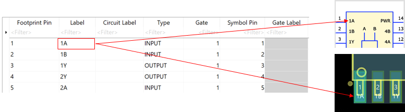
- For non-gated parts, the value in the Label column is used for the symbol pin
in eCADSTAR Schematic Editor
and for the footprint pin in Footprint Editor.
This is illustrated below.
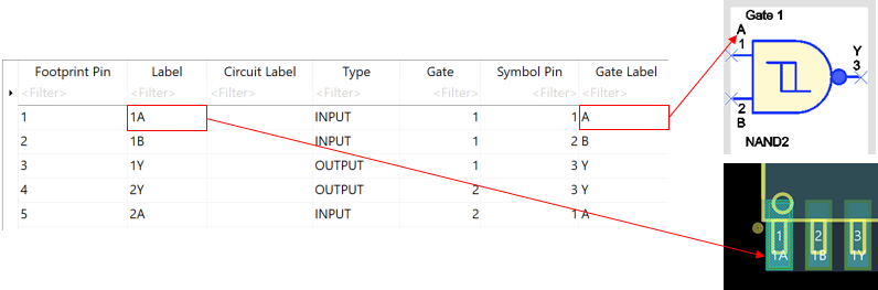
- For gated parts, the value in the Gate
Label column is used for the symbol pin in eCADSTAR Schematic Editor.
However, the value in the Label column
is used for the footprint pin in Footprint Editor.
This is illustrated below.
- If there are unsaved changes in the Detail tab, then the "*" character
is displayed next to the Part Editor
tab.
Assist Menu
