
Task 10: Applying Manual Lengthening
In this topic, you will align routing lengths by applying manual lengthening to routing patterns. You will then recheck the skew results.
-
Using the DIY_HS_1_routed.pdes design from the previous topic, select View > Canvas > Routing Balloon on the eCADSTAR ribbon. The Routing Balloon is displayed on the left side of the canvas.
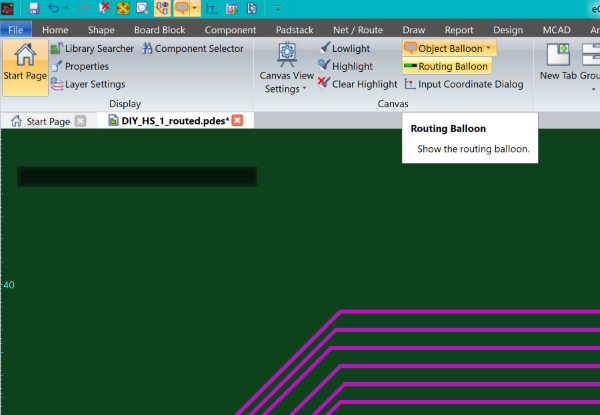
Figure 1: The Routing Balloon
-
In Constraint Browser, select the Skew Groups tab.
- Select the "CLK_TO_ADDRESS_U1-U2" Skew Group.
- In the Skew Groups
tab, select
 . The skew values are shown in red
in the constraints table. This indicates that constraints are not
being met, and that lengthening is required.
. The skew values are shown in red
in the constraints table. This indicates that constraints are not
being met, and that lengthening is required.
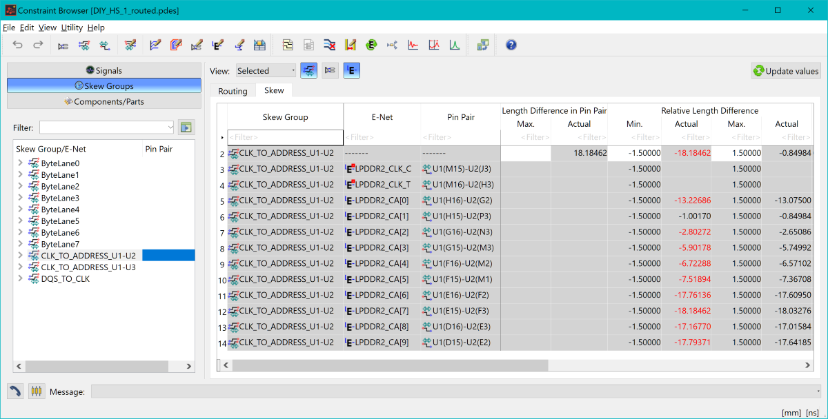
Figure 2: Constraint Browser, Skew Groups tab
- On the ribbon in eCADSTAR PCB Editor, select Net/Route > Routing > Lengthen. The Lengthen command is launched.
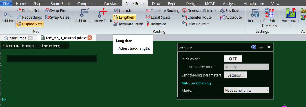
Figure 3: Lengthen Command
With the Push Aside option set to ON, if the Lengthen tool pushes other constrained routing patterns so that they no longer conform to their constraints, then this can cause the process to re-lengthen routing patterns at the end of the operation. This ensures that they meet defined constraints. This process is controlled by selecting Re-lengthen at the end of interactive operations in the Design Settings dialog.
- On the canvas, select the top LPDDR_CA signal on the left side of the branch. If required, the length of the signal is adjusted to meet the required constraints.
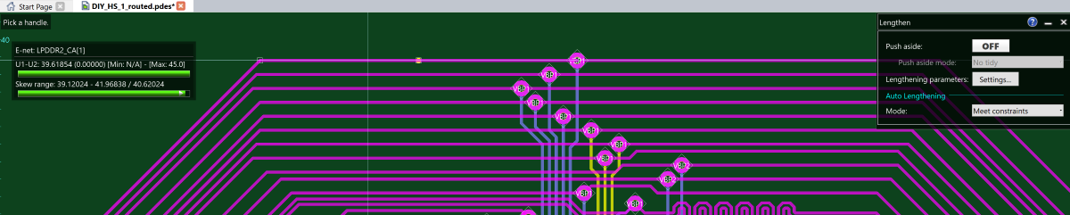
Figure 4: Using the Lengthen Command
The top three signals are already within the skew range relative to the clock, and therefore do not require lengthening. This is indicated in the Routing Balloon.
-
Using the Lengthen command, continue adjusting the length of all other signals on the LPDDR2_CA bus until all signals between U1 and U2 are lengthened, if required.
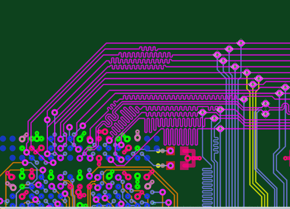
Figure 5: Using the Lengthen Command
In order to meet constraints, CA[6] and CA[8] may require lengthening on Conductor-3, before the Virtual Branch Point.
- Launch Constraint Browser, and select the Skew Groups tab.
- Select the “Clock_to_Address_U1-U2” Skew Group.
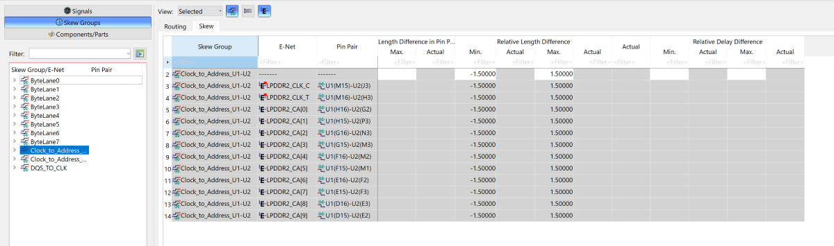
Figure 6: Constraint Browser, Skew Groups tab
- In Constraint Browser, click the button. Actual skew values
are now displayed next to the skew constraint. These are displayed
in black, which indicates that skew constraints are not exceeded.
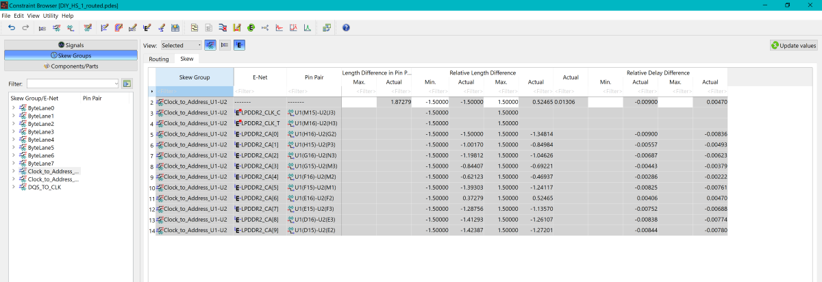
Figure 7: Updating Values
The above procedures are demonstrated in the following video.
This completes the High-Speed DIY training. In this training, you have done the following.
- Created and configured design items, such as Differential Pairs and buses, which are required for High-Speed design.
- Created custom topologies from a predefined topology list, and applied them to signals in Constraint Browser.
- Created Skew Groups using signals within Constraint Browser, and applied constraints.
- Routed to topologies using the tools in eCADSTAR PCB editor.
- Lengthened topologies in order to meet length and skew constraints.
