
The Sheet Settings dialog shows the settings for a selected sheet, and allows you to specify settings for a sheet or multiple sheets when appropriate. It is accessed from the eCADSTAR Schematic Editor ribbon by clicking Sheet > Setting > Sheet Settings, or by clicking Sheet Settings in the Add Sheet or New dialog. If you launch the Sheet Settings dialog from the Add Sheet dialog, then the specified settings are applied to all the added sheets.
Properties tab
In the Property List, the following properties are listed for the selected sheet, in a table format. If an item is editable, then you can apply the specified value to all sheets in the design by selecting the Apply all sheets check box.
| Item | Description | |
|---|---|---|
| Apply all sheets | If an item is editable, then selecting the Apply all sheets check box next to the property being edited, applies the specified value to all sheets in the design. | |
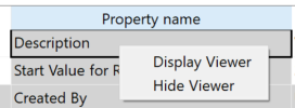
| Property name | The following sheet properties names are displayed. Items can
be edited whose Property value
cell is colored white. The remaining values are read-only.
For each item in the Property
Name column, you can display or hide the associated property
viewer on the canvas by right-clicking the item and selecting
Display Viewer or Hide
Viewer, respectively, on the assist menu.
The property viewer is added to the canvas using the Origin settings that are set in the Application Settings dialog, Display Settings section. |
|
| Description | Allows you to provide a description of the sheet. Select
Apply all sheets to apply the
description to all sheets in the design. Type a value in this box, or enter the description in the Description dialog, over multiple lines. This dialog is launched when you point the cursor in this box, and then click the displayed |
|
| Start Value for Reference Designator | When adding a part to the currently-displayed sheet, this field
allows you to specify the start value for the reference designator.
The value that you specify is shown in the "From" box
in the Add Part
dialog, Range field. It is also
shown in the Reference
Allocator dialog, Initial Value
field, when Selected Items is
selected in the Reference
Allocator dialog. You can select Apply
all sheets to apply this value to all sheets in the design.
Note If you specify a value for a block in the Properties dialog, Start Value for Reference Designator field, then this value cannot be overwritten for individual sheets within the block. |
|
| Created By | The login name for the machine on which the sheet is added. This value is added automatically. | |
| Created Date | The date that the sheet is created. This value is added automatically. | |
| Created Time | The time that the sheet is created. This value is added automatically. | |
| Modified By | The login name for the machine on which the sheet was modified. | |
| Modified Date | The date when the sheet was modified. | |
| Modified Time | The time when the sheet was modified. | |
| Formatted Page Number | Shows the page number relative to the total number of sheets. When you add or delete sheets, you must execute the Page Number command in order for the sheets to be numbered correctly in the Sheet Settings dialog. | |
| Current Page Number | Shows the page number of the current sheet. When you add or delete sheets, you must execute the Page Number command in order for the sheets to be numbered correctly in the Sheet Settings dialog. Change the order of sheets using the Sheet Reorder dialog. | |
| Total Page Number | Shows the total number of sheets. When you add or delete sheets, you must execute the Page Number command in order for the sheets to be numbered correctly in the Sheet Settings dialog. | |
| Design Name | Displays the name of the design. | |
| Design Path | Displays the path to the location of the design. | |
| Design Title | Allows you to optionally specify an alphanumeric title for the design. You can select Apply all sheets to assign this title to all sheets in the design. | |
| Company | Allows you to optionally specify an alphanumeric company name. You can select Apply all sheets to assign this title to all sheets in the design. | |
| Variant Name | If variants exist for the design, then they are displayed. | |
| Property value | Shows the value associated with each property name in the property list. For editable rows, add or change a value by typing in the relevant cell. |
Size/Zone tab
The Size/Zone tab allows you to specify size and zone details for the currently-displayed sheet. Zones define areas of a sheet, based on their X and Y location. Specify these details using one of the following methods:
- Click the Import default settings from Assignments button, and select a template in the Import Default Settings dialog. The details in the template are applied to the currently-displayed sheet.
- Click the Import default settings from Assignments button, and select a template in the Import Default Settings dialog. Change the settings in the Size/Zone tab, and click Apply in the Sheet Settings dialog. The details in the template are applied to the currently-displayed sheet, except where you overwrite them.
- Specify the settings in the Size/Zone tab and click Apply in the Sheet Settings dialog. The settings that you specify are applied to the currently-displayed sheet.
| Item | Description | |
|---|---|---|
| Display sheet background | Allows you to display a background to the sheet. | |
| Selected | Displays the sheet background using the color that you specify in the Display Sheet Background Color box. | |
| Not Selected | The sheet background is not displayed. | |
| Display sheet background color | Allows you to specify a background color for the sheet. Click the Display Sheet Background Color box, and select a color in the Select color dialog. | |
| Specify Color | Selected |
Override the default sheet background color defined in the Assignments dialog, Display tab; use the color defined here instead. Use Color to display the Select color dialog. In the dialog, select a background color for the sheet and click OK. |
| Not Selected | Use the default sheet background color defined in the Assignments dialog, Display tab. | |
| Import default settings from Design Environment | Allows you to update the values in the Size/Zone tab using a template that exists in the library. | |

|
Displays the Import
Default Settings dialog. Select
a template by clicking ,
and selecting it in the displayed Import
Default Settings dialog. |
|
| Display zone | Allows you to specify whether zones are displayed on the sheet using the values specified in the fields below the Size Table. | |
| Display zone color | Allows you to specify the color of the letters or numbers that represent zones. Click the Display Zone Color box, and select a color in the Select color dialog. | |
| Origin X-coordinates | Specify the X coordinate for the origin of the zones. | |
| Origin Y-coordinates | Specify the Y coordinate for the origin of the zones. | |
| Width | Specify the width of the sheet. | |
| Height | Specify the height of the sheet. | |
| Sheet frame symbol name | Displays the name of the border in the currently-displayed sheet. Change the border by clicking Browse and selecting a new border in the displayed dialog. | |
| Browse | Allows you to select a sheet frame symbol file by browsing to it in the displayed dialog. | |
| Horizontal offset | Set the horizontal position for the letters or numbers representing zones. | |
| Vertical offset | Set the vertical position for the letters or numbers representing zones. | |
| Horizontal pitch | Set the horizontal interval for the letters or numbers representing zones. | |
| Vertical pitch | Set the vertical interval for the letters or numbers representing zones. | |
| Horizontal start character | Set the start character that is used for horizontal zones.
|
|
| Vertical start character | Set the start character that is used for vertical zones.
|
|
| Origin |
|
Set the position of the first zone on the sheet. Zones are incremented from the position that you specify. |
| Bottom Left | Zones are incremented starting from the bottom left. | |
| Bottom Right | Zones are incremented starting from the bottom right. | |
| Top Left | Zones are incremented starting from the top left. | |
| Top Right | Zones are incremented starting from the top right. |
Grid tab
Set the properties of the grid that is displayed on the canvas.
| Item | Description | |
|---|---|---|
|
Display |
Selected | The grid is displayed when you click Apply or OK in the Sheet Settings dialog. |
| Not Selected | The grid is hidden when you click Apply or OK in the Sheet Settings dialog. | |
|
Snap grid |
Selected | Objects that are placed on the sheet are snapped to the grid. |
| Not Selected | Objects that are placed on the sheet are not snapped to the grid. | |
| Display color | Allows you to set the color of the grid. Click the Display Color box, and select a color in the Select color dialog. | |
| Horizontal pitch | Set the pitch of the grid in the horizontal direction. | |
| Vertical pitch | Set the pitch of the grid in the vertical direction. | |
| Display grid | Allows you to display a grid mark at multiples of the specified
pitch. For example:
You can snap to a grid line, even when it is not displayed. |
|
| Highlight grid | Allows you to highlight parts of the displayed grid according to the highlight interval that you set. For example, setting a value of 2 highlights every second displayed grid position. |
| Item | Description |
|---|---|
| OK | Applies the changes made in this dialog, and closes it. |
| Cancel | Closes this dialog without applying any changes. |
| Apply | Applies the changes made in this dialog without closing it. |
- If properties that are common to the sheet and the sheet frame are linked, and they are entered at the same time, the sheet frame property has priority.
- If sheet frames are swapped, the property values and property viewers of the sheet frame symbols are always swapped.
