
You can input routing patterns or area fill patterns to the Positive/Negative layer in the same way as for the Positive layer. A cutout can be created for an area fill pattern. The inside of a cutout is handled as a part without a conductor. Therefore, a routing pattern can be added inside the cutout in the same way as for a part without an area fill pattern. This is common both to the Positive layer and to the Positive/Negative layer.
Differences between Positive/Negative layers and Positive layers
Negative data only refers to a thermal land or clearance
land. On the Positive/Negative layer,
when a via that passes through the layer encounters an area fill pattern,
the land is automatically set to a thermal or clearance land which is
defined in the padstack definition. On the Positive
layer, the land is not set to a thermal or clearance land, even if the
via passes through an area fill pattern. Thermal definitions for pins
and vias are set in the Template
Parameters dialog for the positive layer. This dialog is accessed
from the Properties panel when an area
fill is selected. The figure below shows an overview of the Positive/Negative
layer.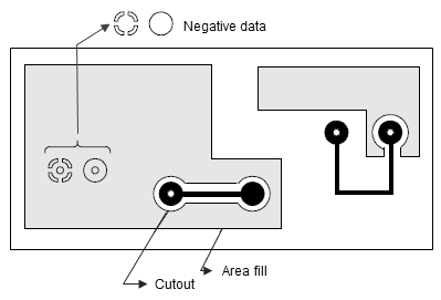
When a complicated shape is represented as a routing pattern, an area fill may be used instead of a general routing pattern. In such a case, it is not appropriate that a via in an area fill is set to a thermal land. Therefore, a layer for a general net should be set as a positive layer. Also, you may want to partially input a thermal land on a specific layer that mainly consists of positive images. Thermal lands cannot be generated on a positive layer, but you can specify them individually in the layout to perform thermal relief.
