
Attribute Text
The Attribute Text command allows you to add component attribute text in eCADSTAR PCB Editor (only available in 2D View mode). Launch this command by clicking Draw > Text > Attribute Text on the ribbon.
Command dialog
Input mode
| Value | Description | ||
|---|---|---|---|
| Reference point | Specify a location for the attribute text by clicking a position on the canvas. | ||
| Type |
A drop down list to specify which component attribute should be printed as text on the canvas. All system and user attributes are available for selection. Note
The active layer will be used as the destination layer for the attribute text. |
||
| Rotation step | Set the angle increment applied when Rotate by Specified Angle on the assist menu is clicked (real number greater than -360 and smaller than 360). | ||
| Text location | Allows you to specify the location of the attribute text in relation to the selected component by defining the parameters in the Attribute Text dialog. Select multiple components using the Ctrl key. | ||
| Type |
A drop down list to specify which component attribute should be printed as text on the canvas. All system and User attributes are available for selection. Note
The active layer will be used as the destination layer for the attribute text. |
||
| Text location | When Input mode is set to Text location, specify the position in which the component symbol is generated. | ||
| Above | The component attribute text is added above the component. | ||
| Below | The component attribute text is added below the component. | ||
| Left | The component attribute text is added to the left of the component. | ||
| Right | The component attribute text is added to the right of the component. | ||
| Center | The component attribute text is added at the center of the component. | ||
| Origin of component | The component attribute text is added at the origin of the component. | ||
| Gap between component and text | When Input mode is set to Text location, set the distance between the target component, and the component attribute text to be added. This option is available when Text location is set to Above, Below, Left, or Right. | ||
| Action for existing data | When Input mode is set to Text location, specify the action for components for which attribute text has already been added. | ||
| No generation | New attribute text is not added. | ||
| Replace | All existing component attribute text is deleted and new attribute text is are added. | ||
| Add | New attribute text are added without deleting the existing text. | ||
| Change at same position | When Input mode is set to Text location and Action for existing data is set to Replace, set whether to add new attribute text in the same positions as the existing ones. | ||
| ON | Attribute text is generated at the same coordinates of the deleted text. This means that the reference points of the generated attribute text is placed on those of the deleted ones. | ||
| OFF | New attribute text is generated in the position specified in Text location, regardless of the positions of the deleted component attribute text. Regardless of whether more than one attribute text is deleted, only one component attribute text will be generated. | ||
| Change by same angle | When Input mode is set to Text location and Action for existing data is set to Replace, set whether to generate new attribute text with the same angle as the replaced attribute text. | ||
| ON | New attribute text is generated with the same angle as the replaced attribute text. | ||
| OFF | New attribute text is generated at the angle that you specify, regardless of the angle of the attribute text. | ||
| Initial angle | Specify the initial angle of the component symbol. |
Characters
| Value | Description | |||||||||||||||||||||
|---|---|---|---|---|---|---|---|---|---|---|---|---|---|---|---|---|---|---|---|---|---|---|
| Font | Select the single-byte font that you want to use. If you
select the zafont0, _zafont0, zpafont0
or _zpafont0 font, then the
following symbols are displayed for the associated character.
|
|||||||||||||||||||||
| Character width | Set the width for text characters (real number equal to or greater than 0). You can also select this from the Font setting dialog. This value refers to the dimensions of the non-displayed box which contains the character, rather than the actual width of the character. | |||||||||||||||||||||
| Character height | Set the height for text characters (real number equal to or greater than 0). You can also select this from the Font setting dialog. This value refers to the dimensions of the non-displayed box which contains the character, rather than the actual height of the character. | |||||||||||||||||||||
| Character spacing | Set the spacing for text characters (Real number equal to or greater than 0). You can also select this from the Font setting dialog. This value refers to the spacing between the non-displayed boxes which contain the characters, rather than the actual spacing between characters. | |||||||||||||||||||||
| Line spacing | Set the line spacing (real number equal to or greater than 0). You can also select this from the Font setting dialog. This value refers to the spacing between the non-displayed boxes which contain the characters in each line of text. | |||||||||||||||||||||
| Pen width | Set the pen width for characters (real number equal to or greater than 0). You can also select this from the Font setting dialog. Because of the method used by eCADSTAR to place text on the canvas, the values that you specify do not refer to the units in the design. | |||||||||||||||||||||
| Select Font sizes | Allows you to specify text size and spacing criteria. Click Select, and then select a row in the Font setting dialog. | |||||||||||||||||||||
| Select | Displays the Font setting dialog. This contains the text size and spacing criteria that you define for eCADSTAR PCB Editor or Footprint Editor. Select a row in the dialog, and click Apply or OK to apply the settings to the Attribute Text dialog. Existing values in the Attribute Text dialog are overwritten by the values that you specify. | |||||||||||||||||||||
| Origin | Specify the anchor position for the attribute text from the following
options. This is shown as a red point on the image that
accompanies each option.
|
|||||||||||||||||||||
| Mirror | Allows you to select whether the attribute text is flipped horizontally when added to the canvas. The setting is saved when the design is saved, and persists after eCADSTAR PCB Editor is closed. | |||||||||||||||||||||
| ON | The attribute text is flipped horizontally when added to the canvas. The Mirror origin position button is made available. This allows you to specify whether the origin of the text string is also flipped horizontally.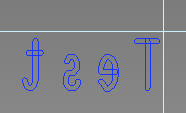 |
|||||||||||||||||||||
| OFF | The attribute text is placed on the canvas in the normal orientation. The Mirror origin position button is made unavailable.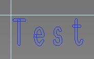 |
|||||||||||||||||||||
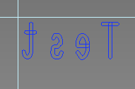
| Mirror origin position | Allows you to select whether the origin of the attribute text that is set in the Origin box is also flipped horizontally. The setting is saved when the design is saved, and persists after eCADSTAR PCB Editor is closed. | |||||||||||||||||||||
| ON | The origin of the attribute text is not flipped when the text string is flipped. The origin is set to Top-left in the following example.
|
|||||||||||||||||||||
| OFF | The origin of the attribute text is flipped horizontally, as well as the text string. The origin is set to Top-left in the following example.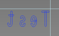 |
Note
When you add text in eCADSTAR, each character is placed within a box, which is not displayed. The values that you specify in the above section refer to the dimensions of this box, rather than the dimensions of the characters. The actual dimensions of characters will vary, depending on their position within this box. This is illustrated in the following image.
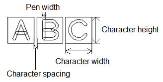
The following applies to text for silkscreen generation:
The silkscreen process in PCB Manufacture is usually a wet process. Consequently, a minimum text height and thickness is required to ensure a good finish for the characters on the silkscreen (legend) layer of the PCB. eCADSTAR PCB Editor provides fonts for the generation of Silkscreen data. As the Character Height and Character Width boxes are larger than the actual character itself, a correction factor must be applied to the character box. This ensures that the text is the correct size. This correction factor is 25% of the character box size.
For example:
When you add text in eCADSTAR, each character is placed within a box, which is not displayed. The values that you specify in the above section refer to the dimensions of this box, rather than the dimensions of the characters. The actual dimensions of characters will vary, depending on their position within this box. This is illustrated in the following image.
The following applies to text for silkscreen generation:
The silkscreen process in PCB Manufacture is usually a wet process. Consequently, a minimum text height and thickness is required to ensure a good finish for the characters on the silkscreen (legend) layer of the PCB. eCADSTAR PCB Editor provides fonts for the generation of Silkscreen data. As the Character Height and Character Width boxes are larger than the actual character itself, a correction factor must be applied to the character box. This ensures that the text is the correct size. This correction factor is 25% of the character box size.
For example:
- For a wet silkscreen process: to obtain a finished text size of 1.5mm (60 thou/mil) it is necessary to create a 1.875mm character box. (Pen width set at 0.15mm / 6 thou/mil).
- For a Laser silkscreen process: to obtain a finished text size of 1.0mm (40 thou/mil) it is necessary to create a 1.25mm character box. (Pen width set at 0.1mm / 4 thou/mil).
It is recommended that you check the capabilities of your PCB manufacturer before creating this data on your PCB.
