
Mapping Power and Ground Global Symbols
This page allows you to set up the symbol alternate CADSTAR Global Symbol to be defined as either a Power or Ground symbol in eCADSTAR.
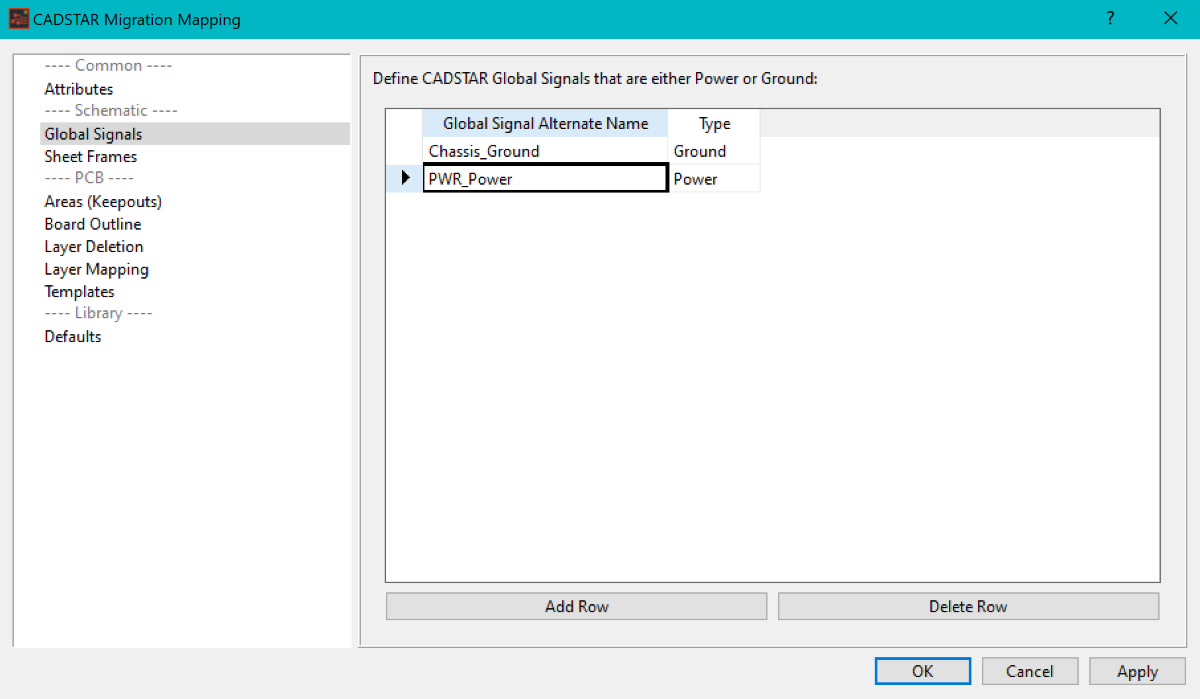
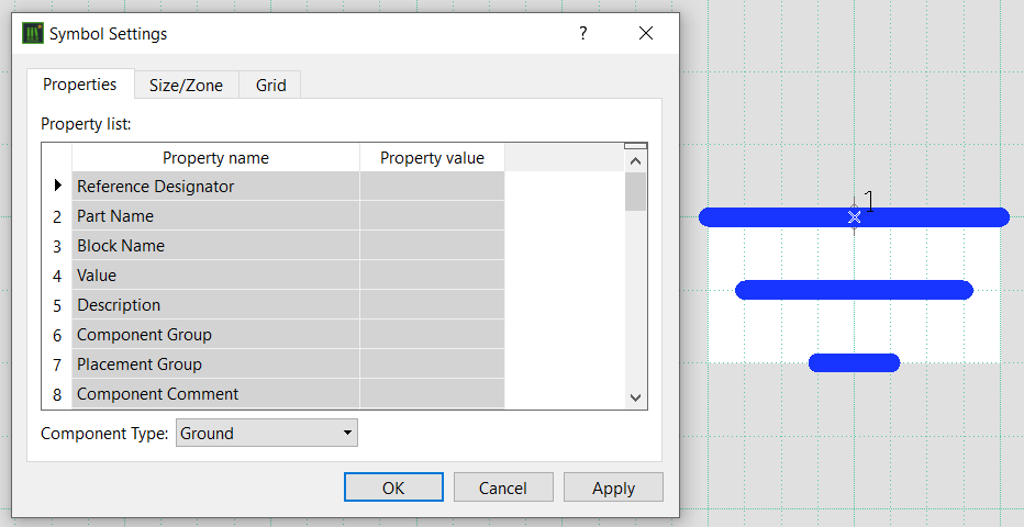
The migration result of the global signal symbol will have its Component Type property defined as Ground or Power.
- Symbols are migrated with a Component Type of Global Connector if they are not defined in this section of the mapping dialog. This means that the nets attached to these nets are considered Signal nets, rather than Power or Ground nets, when being used during the design process. See Appendix D: Global Signals for details on automated power and ground signals.
- This page of the CADSTAR Migration Mapping dialog is referenced when migrating Library and Schematic design data.
Adding Global Signal mapping
-
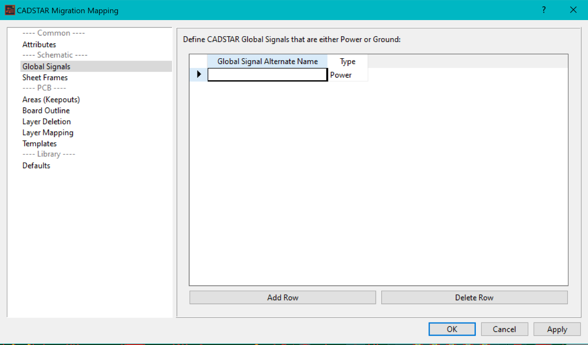
With the Global Signals page of the mapping dialog displayed, click the Add Row button. A new empty row is added to the grid, and the cell in the Global Signal Alternate Name is selected for editing. The Type column defaults to Power.
If existing global signals exist in the grid, then the Add Row button adds a row immediately below the currently-selected row.
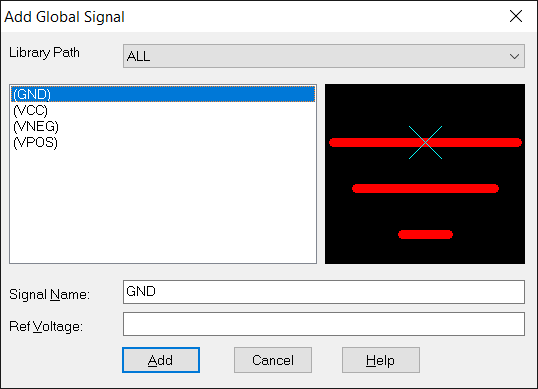
- Type in the CADSTAR Global Signal Alternate Name as defined in the CADSTAR Library or Design.
- In the Type column, set the required type to either Power or Ground.
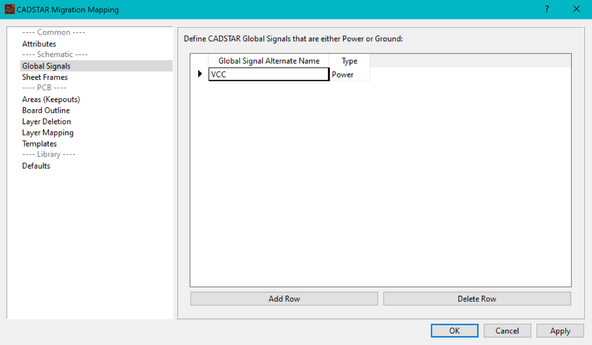
- Click Apply to save the changes and keep the mapping dialog open. Alternatively, click OK to save the changes and close the mapping dialog.
