
CADSTAR Documentation Symbols Library Preparation
This topic provides recommendations for preparing the library data for CADSTAR Documentation Symbols for migration. The CADSTAR to eCADSTAR library migration of documentation symbols requires the documentation symbols to be added into a schematic design, a PCB design or both types of design. This depends on where the documentation symbols are required.
For schematic based documentation symbols.
- Launch CADSTAR Design Editor.
- Select File > New.
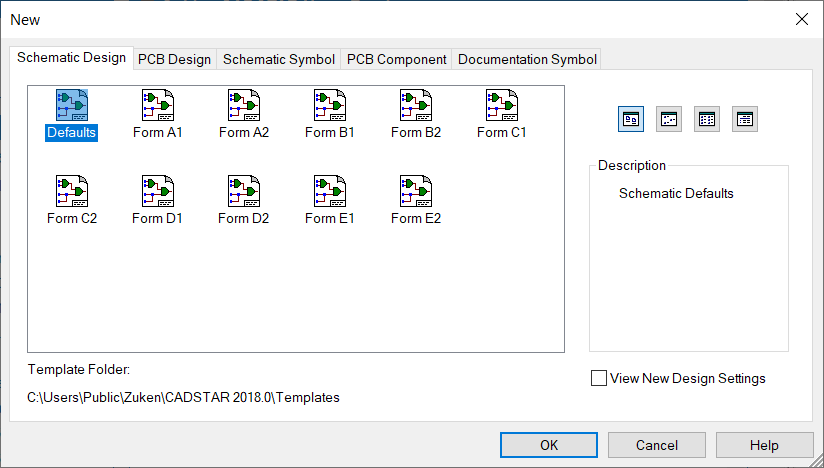
- In the New dialog, select the Schematic Design tab.
- Select a suitable template, such as "Defaults".
- Deselect the View New Design Settings check box, and click OK.
- On the Home tab of the ribbon, select the Part or Symbol split button, and select Doc Symbol. The Add Documentation Symbol dialog is launched.
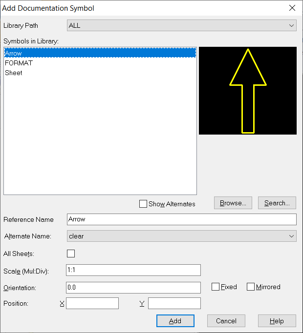
- In the Symbols in Library box, select a required symbol and click Add. The dialog selection is applied, and the documentation symbol is attached to the cursor, ready for placement on the canvas.
- Click a location on the canvas to place the documentation symbol in the design.
As this stage covers the preparation of CADSTAR data, to enable documentation style symbols to be migrated to the eCADSTAR library, placement position is not important.
-
Right-click, and select Cancel on the Assist Menu. Alternatively, press the Escape key once. The Add Documentation Symbol dialog is displayed, ready for the next selection of a documentation symbol required for library migration.
- Repeat the steps to include all required documentation symbols into the design.
- Ensure that all alternates of a symbol are covered by selecting the Alternate Name box.
- When all required symbols are included, exit the Add Documentation Symbol command.
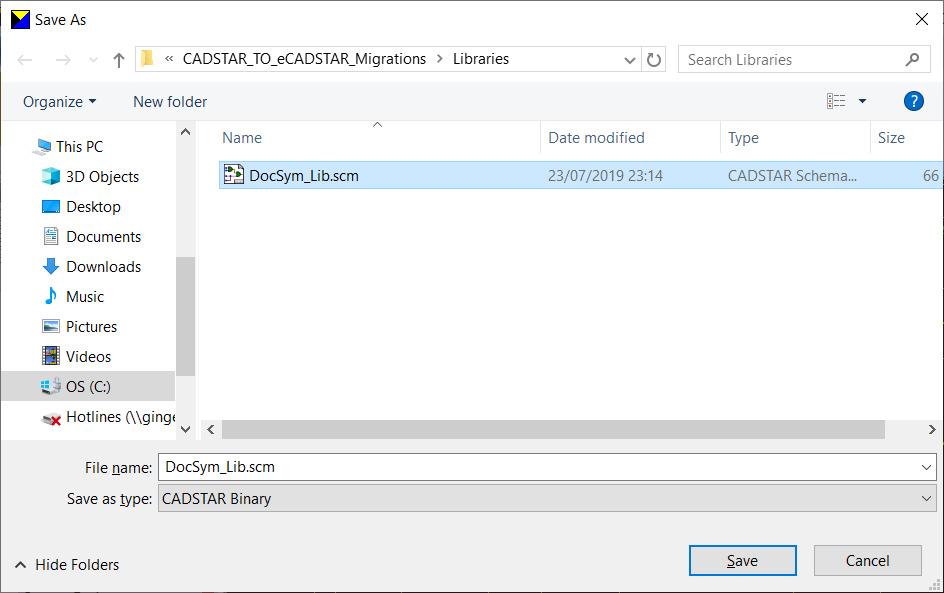
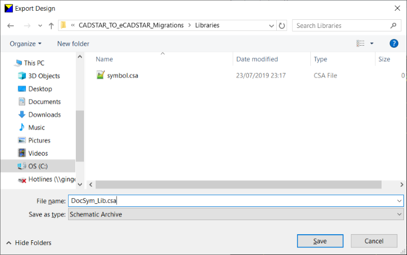
- Select File > Save As to launch the Save As dialog. Select the migration directory defined during the preparation of the part library data for migration, and define the design name as "DocSym_Lib.scm".
- Click Save to apply the settings, and close the dialog.
- Select File > Export. The Export to File dialog is displayed.
- Set the Format option to Schematic Archive.
- Set the Source Sheet option to Whole Design.
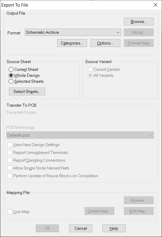
- Click the Browse button. The Export Design dialog is displayed.
- Ensure to set the migration directory defined during the preparation of the part library data for migration. Use the name "DocSym_Lib.csa" for the design file.
- Click Save to apply the settings and close the dialog.
- Click OK on the Export to File dialog. The archive file is generated.
For PCB-based documentation symbols.
- Launch CADSTAR Design Editor.
- Select File > New.
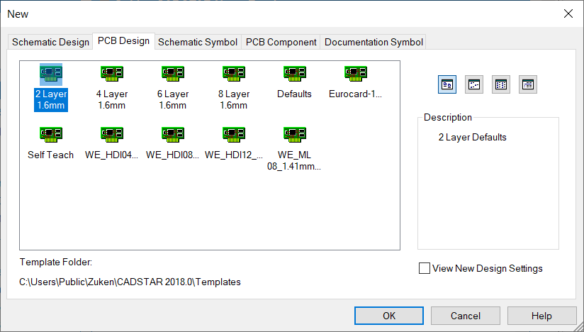
- In the New dialog, select the PCB Design tab and specify a suitable template such as "2 Layer 1.6mm".
- Deselect the View New Design Settings check box, and click OK.
- On the ribbon, select the Part or Component split button in the Home tab.
- Select Doc Symbol. The Add Documentation Symbol dialog is launched.

The documentation symbols for a PCB Design can be placed onto layers with differing types of Non-Electrical and Documentation. Therefore, the requirements of the documentation symbol requirements in eCADSTAR should be considered before migration is performed.
- From the Symbols in Library list, select a required symbol.
- Set the Layer box to the required layer, and click Add. The dialog selection is applied and the documentation symbol is attached to the cursor, ready for placement on the canvas.
- Click a location on the canvas to place the documentation symbol in the design.
Placement position is not important at this stage, as this is preparation of CADSTAR data to enable documentation style symbols to be migrated to the eCADSTAR library.
- Right-click and select Cancel on the Assist Menu. Alternatively press the Escape key once. The Add Documentation Symbol dialog is displayed, ready for the next selection of documentation symbol that is required for library migration.
- Repeat the steps to include all required documentation symbols into the design.
- Ensure all alternates of a symbol are covered by checking the Alternate Name box.
- When all required symbols are included, exit the Add Documentation Symbol command.
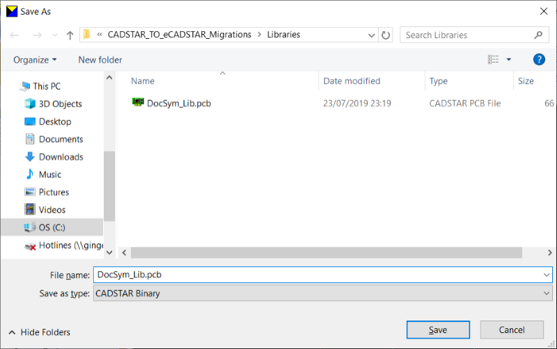
- Select File > Save As. The Save As dialog is displayed.
- Select the migration directory that is defined during the preparation of the part library data for migration.
- Define the design name as "DocSym_Lib.pcb".
- Click Save to apply the settings and close the dialog.
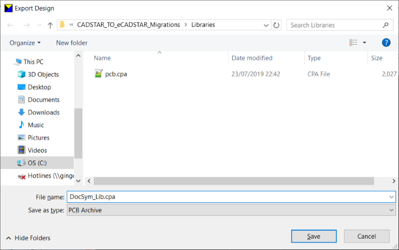
- Select File > Export to open the Export to File dialog.
- Set the Format option to PCB Archive.
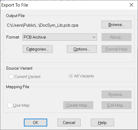
- Click the Browse button to open the Export Design dialog. Ensure to set the migration directory that is defined during the preparation of the part library data for migration. Use the name of the "DocSym_Lib.cpa" design file.
- Click Save to apply the settings and close the dialog.
- Click OK in the Export to File dialog. The archive file is generated. The CADSTAR Documentation Symbol library data preparation is now complete.
