
3D Measure
In 3D View mode, the 3D Measure command allows you to create measurements by selecting a start point, and then an end point on the canvas. Surfaces, edges or vertexes can be selected. The shortest distance is measured between the two selected items. The measured distance is displayed on the canvas as a straight line joining the start and end point, and is labelled as follows:
[Measured distance]
([Distance in the X dimension], [Distance in the Y dimension], [Distance in the Z dimension]).
The measurement results are also shown in an Information box, which is displayed after completing a measurement.
- To launch this command in eCADSTAR PCB Editor, select Home > Dimension > 3D Measure. Alternatively, select MCAD > Dimension > 3D Measure.
- To launch this command in Footprint Editor, select Home > Dimension > 3D Measure. Alternatively, select 3D Model > Dimension > 3D Measure.
Note
- The Advanced 3D license is required to execute this command. To configure licensing, select File > Configuration > Product Settings > License Settings on the ribbon in eCADSTAR PCB Editor and eCADSTAR Library Editor.
- The distance between objects on the canvas is not affected by the Orthographic setting when viewing the canvas in 3D View mode.
| Item | Description | |
|---|---|---|
| Selection Target | Allows you to specify the target for the 3D measurement. All options can be selected. This makes it easier to select a required object on the canvas. | |
| Surface | If selected, then a surface can be selected as a start point
or end point for the 3D Measure
command. A selected surface is highlighted below.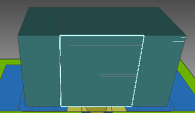 |
|
| Edge | If selected, then an edge of an object can be selected as a
start point or end point for the 3D
Measure command. A selected edge is highlighted below.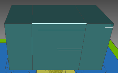 |
|
| Vertex | If selected, then a vertex can be selected as a start point
or end point for the 3D Measure
command. A selected vertex is highlighted below.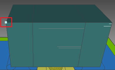 |
