Virtual Decaps
Virtual Decaps can be used inside the PI-Analysis to explore the impact of one or more decoupling capacitors (decaps) on the impedance of the power supply system.
These elements are called "virtual" as they are not actually placed inside the design. They exist purely within the PI Analysis. They are included in all PI Algorithms, such as the computation of the input impedance at an IC's power pin, the 2D impedance distribution, and the impedance spectrum at a user defined location. This topic describes how Virtual Decaps are used in the PI/EMI Analysis Module.
Creating Virtual Decaps
Virtual Decaps (decoupling capacitors) can be added within a power/ground plane pair. To add a new Virtual Decap, the overlapping region of a power and a ground plane must be known by the PI-Algorithm.
- First, perform PI
Analysis
 on
a selected supply system.
on
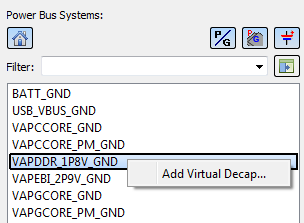
a selected supply system. - In the Power
Bus Systems list, select Add Virtual
Decap on the assist menu to start setting up a Virtual Decap
in the selected supply system.
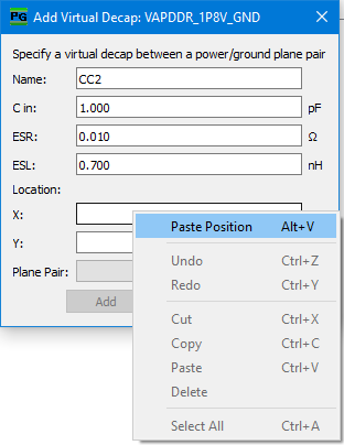
- The Add
Virtual Decap dialog is displayed, as shown below.
| Value | Description | |
|---|---|---|
| Name | Allows you to specify the name of a Virtual Decap. The name is pre-defined with "CC" and a number. This is incremented automatically by one for each new decap in the design. Specify a different name by editing this value. | |
| C in | This value is pre-set with the value specified for RF-circuits in the Options dialog, PI tab. You can also specify a suitable value of your choice. | |
| ESR | This value is pre-set with the value that is specified for RF-circuits in the Options dialog, PI tab. You can also specify a suitable value of your choice. | |
| ESL | This value is pre-set with the value that is specified for RF-circuits in the Options dialog, PI tab. You can also specify a suitable value of your choice. | |
| Location |
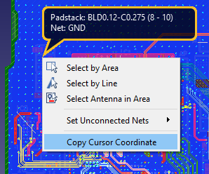
The location of the Virtual Decap is typically retrieved from the canvas. Ideally, by using the impedance map functionality.
Store the selected location in the clipboard by selecting Copy Cursor Coordinate on the assist menu.
Type in valid X, Y coordinates inside one or more overlapping regions of power/ground plane pairs. |
|
| X | The X coordinate of the Virtual Decap | |
| Y | The Y coordinate of the Virtual Decap | |
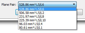
| Plane Pair | Allows you to select between existing overlapping regions,
at this location within the selected supply system. The area of
the overlapping region is shown in the list, as well as the layer
numbers of each plane pair.
|
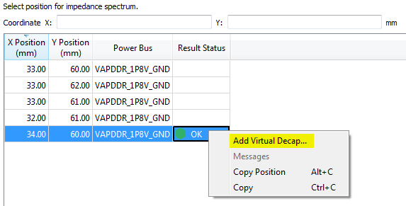
Click Add in the Add Virtual Decap dialog to complete the setup of the Virtual Decap.
Select Add Virtual Decap on the assist menu in the PI table on a selected power bus, and within the PI Spectrum table for any already-defined position. This allows you to easily examine the impact of a decap at a particular position in the power supply system.
Change the values for components in the PI Decap table.
Managing Virtual Decaps
In the PI Decap tab of the Power Bus dialog, the Virtual Decaps (decoupling capacitors) are listed next to the "real" ones, with their name and values. The X and Y position are shown, as previously specified.
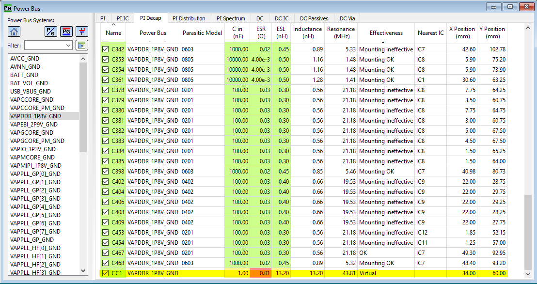
For Virtual Decaps, the Parasitic Model column is empty and the Effectiveness column shows "Virtual". The Name value allows you to identify the Virtual Decaps in the table.
- Change the C in, ESR and ESL values in this table for one or more selected decaps.
- To temporarily disable the Virtual Decap, deselect the Name check box.
- To remove a Virtual Decap from the table and from PI Analysis, right-click in the table and select Remove Virtual Decap on the assist menu.
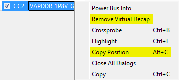
- To make use of this position in the computation of the impedance spectrum at a user-defined position, select Copy Position on the assist menu.
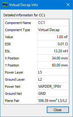
- If you right-click in the Name column and select Component Info on the assist menu, then information is displayed regarding the selected Virtual Decap. For example, the plane pair information.
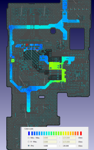
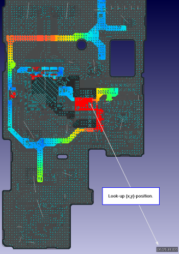
In the following example, a high-impedance area was detected when inspecting the input impedance of a power bus. For a high-impedance resonance frequency, the 2D impedance distribution was computed and inspected in eCADSTAR.
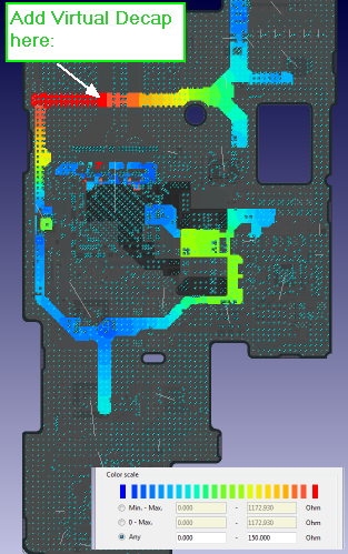
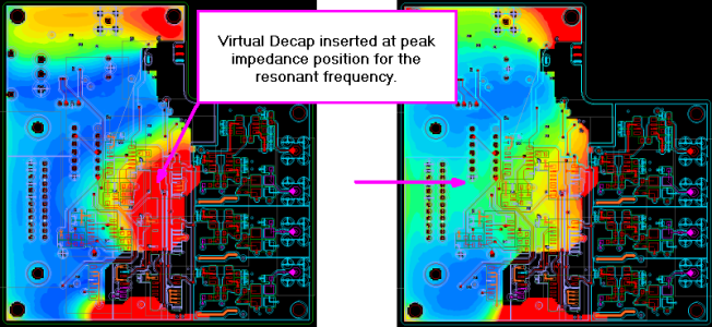
Checking the impedance spectrum at the intended location of a decoupling capacitor (decap), within the high-impedance area, yields inductive behavior and impedance values above 10 Ω from ~400 MHz upwards. This is shown below.
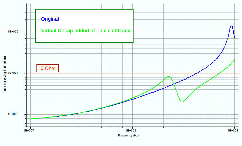
Adding Virtual Decaps (100pF) within the high-impedance area changes the impedance distribution. See the part on the right in the upper image. The impedance spectrum is also changed, and the frequency range below 10 Ω is expanded up to 700 MHz.