
The differential-mode radiation algorithm calculates the radiation from signal trace segments, and their corresponding return currents. Generally, this radiation is small compared with other radiation mechanisms, such as radiation due to common-mode current. This is because the radiation from the signal trace and its return trace or plane tend to cancel in the far field. However, since the differential-mode current can be much larger than the common-mode current, the radiation due to differential-mode currents must still be evaluated.
The following equation describes the maximum electric field strength in a certain distance R from an electrically-small current loop.
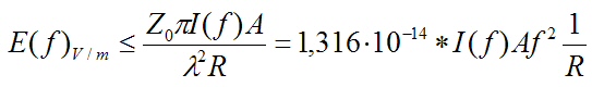
The distance R must be within the far field range. In the PI/EMI analysis module, a minimum Antenna Distance of 3m is required.
The main parameters in this equation are as follows.
- Spectrum of the signal current I(f): this is influenced by the Driver, Receivers and Terminations, etc.
- Frequency f: this occurs as the square of f. Therefore, higher frequencies typically dominate the DM emission.
- Loop Area A: this is usually determined by the distance to the closest-neighbored reference plane of each net-segment. If no reference planes are close, then adjacent tracks might provide the return path. The trace length on the top or bottom layer (microstrip lines) is an important consideration. Shielded tracks on inner layers (stripline configurations) are treated as shielded. They do not contribute to the DM emission.
