The Align Component
command allows you to move and align multiple components by dragging them
on the canvas, or by specifying a reference component . Click Component
> Placement >  Align
Components on the ribbon in eCADSTAR PCB Editor.
The Align Component dialog is displayed.
Align
Components on the ribbon in eCADSTAR PCB Editor.
The Align Component dialog is displayed.
Align mode
| Value | Description |
|---|---|
| Drag | If selected, you can move and align multiple components by selecting them on the canvas, and then dragging them. Select each component using the Ctrl key, and then right-click and choose Selection End on the assist menu. Specify the destination to move them to by clicking a position on the canvas. The selected components are aligned using the settings that you specify in this dialog. If you select this option, then the Drag options section is made available. |
| Reference | If selected, you can move and align multiple components by selecting a reference component on the canvas. After you specify a reference component, select the components to align with it by clicking them using the Ctrl key. The selected components are aligned with the reference component using the settings specified in this dialog. The Drag options section is made unavailable. |
Base options
Target of base
| Value | Description | |
|---|---|---|
| Component area | Allows you to align components using the edge of the component area that you specify. | |
| Base |
| |
| Reference point | Allows you to align components by specifying a horizontal or vertical line through the component origin. | |
| Base |
| |
| Pin | Allows you to align components using the position of their pins. | |
| Base |
|
Specify gap
| Value | Description | |
|---|---|---|
| ON | If selected, then you can specify the gap between neighboring
components by adding a value in the Specified
value field, or by specifying that this is set using the
relevant design rule.
|
|
| OFF | The gaps between components remain the same as they were before being moved. | |
| Gap | This field is made available when Target of base is set to Component area. It allows you to either specify that the gap between components is set using the Clearance (Component area - Component area) rule in the Rule Editor dialog, or by specifying a value. | |
| Rule | If selected, then the gap between components is specified by the Clearance (Component area - Component area) rule. This is set in the Rule Editor dialog, Placement tab. | |
| Specified value | If selected, then the gap between components is specified by the value that you enter in the Specified value box. | |
| Specified value | Components are spaced using the specified gap. Enter a real number equal to or greater than 0. |
Drag options
This section is made available if you select Drag in the Align mode section.
| Value | Description | |
|---|---|---|
| Rotation step | Specify the rotation angle that is applied when you select Rotate by Specified Angle on the assist menu. Specify a real number greater than -360 and smaller than 360. | |
| Placement specified by circuit | For components that you drag on the canvas in eCADSTAR PCB Editor, this setting allows you to specify that their position relative to each other is maintained, which is defined on the canvas in eCADSTAR Schematic Editor. In eCADSTAR Schematic Editor, toggle on the Auto Send command, and then select the components on the canvas that you want to move. The components are selected on the canvas in eCADSTAR PCB Editor, and can be dragged to the required position. | |
| ON | The position of the dragged components, relative to each other, is defined on the canvas in eCADSTAR Schematic Editor. The Expanded pitch for comp. area field is made available. In eCADSTAR Schematic Editor, toggle on the Auto Send command, and then select the components on the canvas that you want to move. | |
| OFF | The relative position of the dragged components is defined in the Base Options section in this dialog. | |
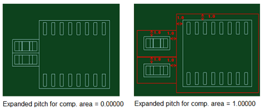
| Expanded pitch for comp. area | Allows you to specify a gap around the component areas. If
you specify a value of "0", then no gap is added. If
you specify a value greater then "0", then the specified
gap is added around each component area. This is illustrated below.
|