Linear Dimension (Single)
The Linear Dimension (Single)
command allows you to input a single linear dimension in Footprint Editor. It is
executed by clicking split button , or on the ribbon. The dimension is added to the user-defined
layer that you select in the displayed Linear
Dimension (Single) dialog. You can change the properties of the
dimension line by selecting it on the canvas, and then editing the settings
in the Properties
panel. To change the dimension value and the position of the dimension
line, set Edit dimension to ON,
and then drag the dimension line on the canvas. This command is only available
in 2D View mode.
Command dialog
Layer name
| Value |
Description |
| User-defined drawing layers. |
Allows you to select a drawing layer. All user-defined drawing
layers are displayed. |
Dimension direction
| Value |
Description |
| Horizontal/Vertical
|
Automatically determines the dimension line for both horizontal
and vertical directions from the mouse position. |
| 2 points
|
Inputs dimension lines in parallel to the specified points. |
Arrow direction
| Value |
Description |
| Inward
|
The direction of the arrow is inward. |
| Outward
|
The direction of the arrow is outward. |
Aux line at start point
| Value |
Description |
| ON
|
An auxiliary line is displayed on the start point side. |
| OFF
|
No auxiliary line is displayed on the start point side. |
Aux line at end point
| Value |
Description |
| ON
|
An auxiliary line is displayed on the end point side. |
| OFF
|
No auxiliary line is displayed on the end point side. |
Arrow type
| Value |
Description |
| No arrow
|
The arrow type at the start point is set to no
arrow. |
| Circular arrow
|
The arrow type at the start point is set to circular. |
| Closed arrow
|
The arrow type at the start point is set to closed. |
| Open arrow
|
The arrow type at the start point is set to open. |
Dimension text attributes
| Value |
Description |
| Defaults
|
Displays the Design
Settings dialog. This allows you to set the Dimension
Text values, which are shared between multiple commands. |
Tolerance text
| Value |
Description |
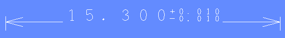
| ON
|
Positive and negative manufacturing tolerances are displayed
on the canvas for dimension lines that you add using a dimension
command. This is illustrated in the following example.
The Positive Tolerance
and Negative Tolerance fields
are made available. The values that you specify in these
fields are displayed in the relevant dialog for every dimension
command.
|
| OFF
|
Tolerances are not displayed on the canvas for dimension lines.
The Positive Tolerance and Negative Tolerance fields are made
unavailable. |
Note
If you change the units in a design, the
tolerances that you specify are not changed.
Positive Tolerance
| Value |
Description |
| Real number greater than or equal to 0. |
Specify the positive tolerance for all dimension lines that
you add using a dimension command. The value that you specify
is displayed on the canvas, with a "+" prefix. It is
displayed after the dimension value. |
Negative Tolerance
| Value |
Description |
| Real number greater than or equal to 0. |
Specify the negative tolerance for all dimension lines. The
value that you specify is displayed on the canvas, with a "-"
prefix. It is displayed after the dimension value. |
Edit dimension
| Value |
Description |
| ON
|
Allows you to change the dimension value and the position of
any dimension line that you select on the canvas. |
| OFF
|
You cannot edit dimension lines that you select on the canvas. |

 Single, or Draw > Linear Dimension
>
Single, or Draw > Linear Dimension
> 