
The Design Settings dialog allows you to set the Dimension
Text, Dimension Display and Snap values for relevant commands in Footprint Editor. This dialog
is displayed by clicking Defaults in a
command dialog, or by clicking Design> Settings >  Design
on the Footprint Editor
ribbon.
Design
on the Footprint Editor
ribbon.
Dimension Text
Precision (Dimension)
| Value | Description |
|---|---|
| 0-5 | Specify the number of decimal places for the dimension value. |
Precision (Tolerance)
| Value | Description |
|---|---|
| Same as dimension. | Sets the number of decimal places for the tolerance value to be the same as for the dimension value. |
| 0-5 | Specify the number of decimal places for the tolerance value. |
Zero suppression
| Value | Description |
|---|---|
| Never | Zeros are never suppressed in the dimension value. For example: "0.100" is displayed when the precision is 3. |
| Decimal only | Zeros are only suppressed in the decimal part of the dimension value. For example: "0.1". |
| Integer only | Zeros are only suppressed in the integer part of the dimension value. For example: ".100". |
| Both | Zeros are suppressed for the decimal and integer parts of the dimension value. For example: ".1". |
Offset from Dimension
| Value | Description |
|---|---|
| Real number. | The offset for the text from the dimension, specified in the currently-defined units. |
Font
| Value | Description |
|---|---|
| (Font values) | Select a single byte font for the text that is used to display dimensions. |
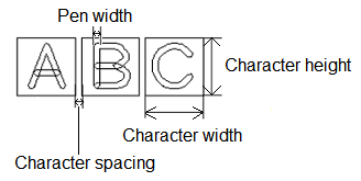
Character width
| Value | Description |
|---|---|
| Real number greater than 0. | Set the width for text characters (real number equal to or greater than 0). You can also select this from the Font setting dialog. This value refers to the dimensions of the non-displayed box which contains the character, rather than the actual width of the character. |
Character height
| Value | Description |
|---|---|
| Real number greater than 0. | Set the height for text characters (real number equal to or greater than 0). You can also select this from the Font setting dialog. This value refers to the dimensions of the non-displayed box which contains the character, rather than the actual height of the character. |
Character spacing
| Value | Description |
|---|---|
| Real number greater than 0. | Set the spacing for text characters (Real number equal to or greater than 0). You can also select this from the Font setting dialog. This value refers to the spacing between the non-displayed boxes which contain the characters, rather than the actual spacing between characters. |
Select font sizes
| Value | Description |
|---|---|
| Select | Displays the Font setting dialog. This contains the text size and spacing criteria that you define for eCADSTAR PCB Editor or Footprint Editor. Select a row in the dialog, and click Apply or OK to apply the settings to the Design Settings dialog. Existing values in the Design Settings dialog are overwritten by the values that you specify. |
Origin
| Value | Description |
|---|---|
| (Justification) | Specify the reference point for characters from the following
options. The origin is shown as a red point on the image that
accompanies each option.
|
Dimension Display
Arrow Length L
| Value | Description |
|---|---|
| Real number greater than 0. | Set the length of the arrow "head".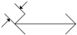 |
Arrow Angle A
| Value | Description |
|---|---|
| Integer between 1 and 90. | Set the angle of the arrow "head".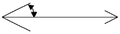 |
Circle diameter D
| Value | Description |
|---|---|
| Real number greater than 0. | Set the diameter of the circle associated with an arrow.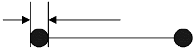 |
Offset dimension O1
| Value | Description |
|---|---|
| Real number equal to or greater than 0. | Set the offset value shown below for a dimension line.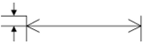 |
Offset aux line O2
| Value | Description |
|---|---|
| Real number equal to or greater than 0. | Set the space for starting an extension line from the dimension
reference point.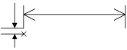 |
Line width
| Value | Description |
|---|---|
| Real number equal to or greater than 0. | Set the pen width for drawing dimension lines. |
Snap
Allows you to configure the Snap
function (2D View mode only) in Footprint Editor. This function
is used to snap to existing objects on the canvas when executing a command.
When the position of an object on the canvas is identified, the "Flag"
icon is displayed and the cursor is snapped to its coordinates. When the
Snap command is toggled on, the following
icon is displayed at the cursor position:  . This section
of the Design Settings dialog is displayed
by clicking the Snap split button
on the status bar and then selecting Snap Settings.
. This section
of the Design Settings dialog is displayed
by clicking the Snap split button
on the status bar and then selecting Snap Settings.
Snap
| Value | Description | |
|---|---|---|
| Only allow snap point selection | Allows you to specify whether a snapping position must be identified before a relevant command can be executed. | |
| Selected | The relevant command cannot be executed unless a snapping position is identified.. | |
| Not Selected | The relevant command can be executed, regardless of whether a snapping position is identified. | |
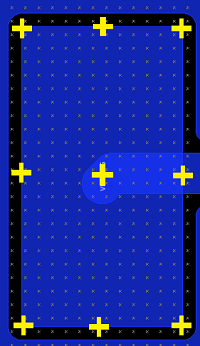
| Multiple Pad/Padstack reference points | For a non-circular pad or padstack, this setting allows you to snap only to its center, or to the vertices and mid points of its segments, as well as to its center. | |
| Selected |
For a non-circular pad or padstack, you can snap to its center, as well as to its vertices and the mid points of its segments. These snap points are illustrated below for a rectangular padstack.
|
|
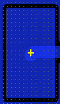
| Not Selected |
For a non-circular pad or padstack, you can snap only to its center. This snap point is illustrated below for a rectangular padstack.
|
Arc
Allows you to snap to the middle point or center point of an arc.
| Value | Description |
|---|---|
| Middle point | If selected, a flag icon is displayed at the middle point of the arc, and the cursor is snapped to it. |
| Center point | If selected, a circle is displayed at the center point of the arc. This enables you to select this position when executing a command. |
Target layer
Allows you to specify the layer for which the Snap function applies.
| Value | Description | |
|---|---|---|
| Visible layer | The Snap function applies to objects on the visible layer. | |
| Specify layer | The Snap function applies to objects on the layer that you select in the Layer box in the Target layer group. If selected, the Layer box is made available. | |
| Layer box | Specify the layer for which the Snap function applies. |
Objects
Allows you to select the type of object on the canvas for which the Snap function applies.
| Value | Description |
|---|---|
| Type | Select the type of object for which the Snap
function applies. The following types of object can be selected.
|
This dialog is used by the following commands:
Linear Dimension (Single)
Linear Dimension (Series)
Linear Dimension (Parallel)
Linear Dimension (Increment)
Dimension Line (Diameter)
Dimension Line (Radius)
Leader Dimension (Polygonal Line)
Angle Dimension (Angle)
Angle Dimension (Arc Length)
