

The Basic Settings tab on the Output (Drill Data) dialog allows you to specify the output folder that the drill data is exported to. It also allows you to specify an NCF file and table file, and edit these files using the NCF Editor and Table Editor dialogs. The Coordinates settings section allows you to specify the area of the board from which the drill data is exported. It also allows you to rotate, scale or offset the exported drill data. The Toolpath Sorting section allows you to specify the method that is used to export the drill data from the board. The Drill process section allows you to specify the drill processes that are exported. These are created in the Drill Process Settings tab, Drill process section.
When you generate a drill table from a PCB design, any text on the relevant drill drawing layer is deleted, regardless of whether it is inside or outside the board area.
Output
Manufacturing rule
| Value | Description | |
|---|---|---|
| NCF file | Displays the NCF file that you select by clicking  . This file specifies
the format of the positional data that is used by drilling machine,
and allows you to accommodate differences in drilling machines. . This file specifies
the format of the positional data that is used by drilling machine,
and allows you to accommodate differences in drilling machines. |
|
|
|
Allows you to select an NCF file in the displayed Open dialog. Various NCF files are provided at the following location: [installation folder]\eCADSTAR\eCADSTAR [version]\settings.ncs\ncf. | |
| Assign tool code | Auto |
Automatically populates the drill output file with the tool data that is extracted from the board. This is the recommended settings. |
|
Manual |
Assigns a tool code by referencing the table file that you
select by clicking . If
Manual is selected, then the
Table file box and button are made available.
This setting could be used if a limited number of tools are available
in the CAM process, as it allows you to manually specify the tool
data. |
|
| Edit NCF | Displays the NCF Editor dialog. This dialog allows you to configure the format of the NCF file that is referenced when drill data is generated. | |
| Table File | Displays the table file that you select by clicking . If you select Manual, then this field is made available.
Specifying a table file allows you to define the drill types,
including their shape and size, and the hole type.
Note The specified table file is automatically checked, and an error is displayed if it does not contain all the required tool sizes for the board. |
|
|
|
Allows you to select a .table file in the displayed Open dialog. The aperture.table and tool.table files are provided at the following location: [installation folder]\eCADSTAR\eCADSTAR [version]\settings.ncs\tbl. The recommended option is tool.table. | |
| Edit Table | Displays Table Editor dialog. This dialog allows you to edit the table file that is shown in Table file box. You can specify values for aperture shapes and tools, and also merge values from another table file. If you have not specified a table file, then clicking Edit Table allows you to create one, and set the relevant values in the Table Editor dialog. A dialog is displayed which allows you to create the new table file. If you click Yes in this dialog, then the New (Table dialog is displayed. |
Coordinates settings
| Value | Description | |
|---|---|---|
| Specify output area | Allows you to specify whether drill data is exported from the whole board, or only from a specified area. | |
| Selected | Allows you to define a rectangular output area by specifying the coordinates of its start and end points on the board. Drill data is exported that is only in the area defined by the specified start and end points. When selected, the fields in the Specify output area section are made available. | |
| Not-selected | All of the drill data on the board is exported. The fields in this section are made unavailable. | |
| Start point |
|
|
| End point |
|
|
| Reference point | Allows you to define the centre point that is used by the Rotate and Scale commands. The exported drill data is rotated or scaled using the specified location as a reference point. Specify its coordinates in the X and Y fields. | |
| X | Specify the X coordinate of the centre point that is used by the Rotate and Scale commands. Specify a real number between -5000.0 and 5000.0 mm. | |
| Y | Specify the Y coordinate of the centre point that is used by the Rotate and Scale commands. Specify a real number between -5000.0 and 5000.0 mm. | |
| Rotate | Allows you to rotate the coordinate system of the exported drill data. | |
| 0-degree (No rotation) | The exported drill data is not rotated. | |
| 90-degree | The coordinate system of the exported drill data is rotated 90 degrees counterclockwise. | |
| 180-degree | The coordinate system of the exported drill data is rotated 180 degrees counterclockwise. | |
| 270-degree | The coordinate system of the exported drill data is rotated 270 degrees counterclockwise. | |
| Scale | Allows you to change the size of the exported data by a specified
value. The hole diameters are not changed. Specify a real number
between 0.02 and 50.0.
|
|
| Offset | Allows you to offset the coordinates of the exported data by a specified amount, or offset them to a specified position. Specify a real number between -5000.0 and 5000.0 mm. If units other than mm are used, then equivalent values are applied. | |
| Specify offset value | Allows you to specify the values in the X and Y dimensions by which the exported drill data is offset. If you specify "0" in the X and Y fields, then the exported drill data is not offset. In the [Drill process name].fdl file that is created, the value is updated in the Moved Dis. column in the Tool Count table for drill code T01. | |
| Specify placement point | Allows you to specify the X and Y coordinates of the position that the exported drill data is offset to. If you specify "0" in the X and Y fields, then the exported drill data is not offset. In the [Drill process name].fdl file that is created, the value is updated in the Moved Dis. column in the Tool Count table for drill code T01. | |
| X |
|
|
| Y |
|
Toolpath Sorting
| Value | Description | |
|---|---|---|
| Sort mode | Allows you to specify the method that is used to export the drill data from the board. You can specify that it is exported from the board in either horizontal or vertical bands for all tool sizes. Alternatively, you can specify that it is exported for each tool size, for the whole board. You can also specify that toolpath sorting is not done. | |
| OFF | The drill data is exported from the board without using toolpath sorting. The Bandwidth box is made unavailable. | |
| Band sort (X-axis) | The drill data is exported from the board in horizontal bands for all tool sizes. Specify the width of the bands in the Bandwidth box. Specify a real number between 1.0 and 5000.0 mm. If units other than mm are used, then equivalent values are applied. If selected, then the Bandwidth box is made available. | |
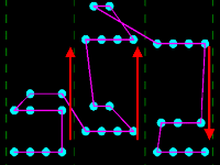
| Band sort (Y-axis) |
The drill data is exported from the board in vertical bands for all tool sizes. Specify the width of the bands in the Bandwidth box. Specify a real number between 1.0 and 5000.0 mm. If units other than mm are used, then equivalent values are applied. If selected, then the Bandwidth box is made available. The tool path that is used is shown below.
|
|
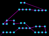
| N sort |
The drill data is exported For each tool size, in sequence, beginning with the hole that is nearest is to the origin. The Bandwidth box is made unavailable. This is illustrated below.
|
|
| Bandwidth | If you select Band sort (X-axis) or Band sort (Y-axis) , then this box is made available. Specify the width of the horizontal or vertical bands of drill data that are exported from the board. Specify a real number between 1.0 and 5000.0 mm. If units other than mm are used, then equivalent values are applied. |
Drill Process
| Value | Description | |
|---|---|---|
| Drill process table | Allows you to specify the drill processes that are exported,
and change the order in which they are displayed in this table.
The drill processes are created in the Drill
Process Settings tab, Drill process
section. If you select the Output
box for a drill process, then the following files are created
in the specified output folder:
|
|
| Output | If selected, then the associated drill process is exported to the specified output folder. | |
| Drill process name | Displays the name of the drill processes that you create in the Drill Process Settings tab, Drill process section. | |

|
Moves the selected drill process to the top of the Drill process tables in the Basic Settings and Drill Process Settings tabs. This setting changes only the order in which they are displayed in these tables. | |

|
Moves the selected drill process up one position in the Drill process tables in the Basic Settings and Drill Process Settings tabs. This setting changes only the order in which they are displayed in these tables. | |

|
Moves the selected drill process down one position in the Drill process tables in the Basic Settings and Drill Process Settings tabs. This setting changes only the order in which they are displayed in these tables. | |

|
Moves the selected drill process to the bottom of the Drill process tables in the Basic Settings and Drill Process Settings tabs. This setting changes only the order in which they are displayed in these tables. |
