

The Design Environment dialog allows you to configure the color and format of sheets, and specify their associated properties. It also allows you to configure zones, symbols and the properties of grids and hierarchy blocks. Zones define areas of a sheet, based on their X and Y location. The settings that you specify are applied to eCADSTAR Schematic Editor and Symbol Editor, where applicable. This dialog is displayed as follows:
- In eCADSTAR Library Editor: click Home > Schematic Resources > Design Environment.
- In eCADSTAR Schematic Editor: click Design > Settings > Design Environment.
When this dialog is displayed in eCADSTAR Schematic Editor, the displayed settings are read-only. To update the environment settings in eCADSTAR Schematic Editor to match the current library, click the Update button.
Sheet Size
The Sheet Size tab allows you to configure the color and format of sheets and zones in eCADSTAR Schematic Editor.
| Value | Description | |
|---|---|---|
| Sheet Background Color for creating sheet | Allows you to specify the background color of a new sheet in eCADSTAR Schematic Editor. Select a color in the Select color dialog and click OK. | |
| Zone Color for creating sheet | Allows you to specify the color of zones in a new sheet in eCADSTAR Schematic Editor. Select a color in the Select color dialog and click OK. | |
| Size Table | Displays the sheet formats that are available in eCADSTAR Schematic Editor, and allows you to configure them as templates. These templates can be selected in the Import Default Settings dialog in eCADSTAR Schematic Editor. | |
| Number | Displays the read-only number that is associated with each sheet format. | |
| Displayed Name | Allows you to specify a meaningful name for each sheet format. | |
| X origin | Allows you to set the X position of the sheet origin, relative to the sheet frame. If a value of "0" is specified, the sheet origin is set at the left of the sheet frame. | |
| Y origin | Allows you to set the Y position of the sheet origin, relative to the sheet frame. If a value of "0" is specified, the sheet origin is set at the bottom of the sheet frame. | |
| X Size | Allows you to specify the sheet size in the X dimension as a real number. | |
| Y Size | Allows you to specify the sheet size in the Y dimension as a real number. | |
| Sheet Frame Symbol Name | Allows you to specify the name and alternate of the sheet frame symbol that is displayed on the relevant sheet in eCADSTAR Schematic Editor. | |
| Offset Mode | Allows you to select the offset mode for zone labels on the
schematic sheet. The following options can be selected.
|
|
| X Offset | Allows you to specify the horizontal offset value for zones on a schematic sheet. This value can only be specified when Manual is selected in the Offset Mode box. | |
| Y Offset | Allows you to specify the vertical offset value for zones on a schematic sheet. This value can only be specified when Manual is selected in the Offset Mode box. | |
| X Pitch | Allows you to specify the horizontal interval for zones on a schematic sheet. | |
| Y Pitch | Allows you to specify the vertical interval for zones on a schematic sheet. | |
| X Start Char | Allows you to set the start character for horizontal zones. This must be a letter or number that is one character long. | |
| Y Start Char | Allows you to set the start character for vertical zones. This must be a letter or number that is one character long. | |
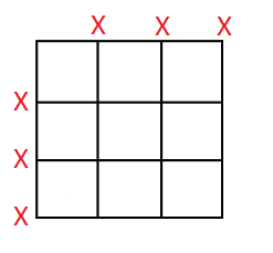
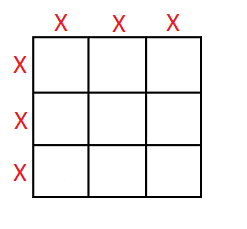
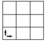
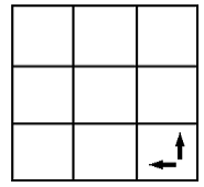
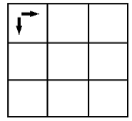
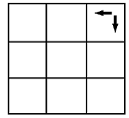
| Zone Origin | Allows you to specify the origin of the zones on a schematic
sheet. The following options are available.
|
Symbol Size
The Symbol Size tab allows you to configure the color of symbols and associated zones in eCADSTAR Schematic Editor and Symbol Editor, where applicable, and specify the template that is used by default when creating symbols.
| Value | Description | |
|---|---|---|
| Symbol Background Color for creating symbol | Allows you to specify the color of symbols in eCADSTAR Schematic Editor, and Symbol Editor. Select a color in Select color dialog and click OK. | |
| Zone Color for creating symbol | Allows you to specify the zone color for symbols in eCADSTAR Schematic Editor, and Symbol Editor. Select a color in Select color dialog and click OK. | |
| Component Type for creating symbol | Allows you to specify the template that is used by default when creating symbols. Select a component type from the box. | |
| Figure | The template symbol for figures is used by default when creating symbols. | |
| Sheet Frame | The template symbol for sheet frames is used by default when creating symbols. | |
| Parts | The template symbol for parts is used by default when creating symbols. | |
| Gate | The template symbol for gates is used by default when creating symbols. | |
| Power Box | The template symbol for power boxes is used by default when creating symbols. | |
| Power | The template symbol for power connections is used by default when creating symbols. | |
| Ground | The template symbol for ground connections is used by default when creating symbols. | |
| Hierarchy Connector | The template symbol for hierarchy connectors is used by default when creating symbols. | |
| Sheet Connector | The template symbol for sheet connectors is used by default when creating symbols. | |
| Global Connector | The template symbol for global connectors is used by default when creating symbols. |
Grid
The Grid tab allows you to set the properties of the grid that is displayed on the canvas.
| Value | Description | |
|---|---|---|
| Display | If selected, a grid is displayed on the canvas. | |
| Snap Grid | If selected, objects that you add to the canvas are snapped to the grid lines. | |
| Display Color | Allows you to specify the color of grids by selecting a color in the Select color dialog. | |
| Horizontal Pitch | Set the pitch of the grid in the horizontal direction. | |
| Vertical Pitch | Set the pitch of the grid in the vertical direction. | |
| Display Grid |
Allows you to display a grid mark at multiples of the specified pitch. For example:
You can snap to a grid line, even when it is not displayed. |
|
| Highlight Grid | Allows you to highlight parts of the displayed grid according to the highlight interval that you set. For example, setting a value of 2 highlights every second displayed grid position. |
Block
For the hierarchy blocks that you create in eCADSTAR Schematic Editor, the Block tab allows you to specify the prefix that is used in the Reference field, and the symbol and alternate symbol used for each type of hierarchy connector.
| Value | Description | |
|---|---|---|
| Reference Header | Allows you to specify the prefix that is used in the Reference field for the hierarchy blocks created in eCADSTAR Schematic Editor. | |
| Hierarchy Connector Symbol | Allows you to specify the symbol and alternate symbol that is used for each type of hierarchy connector in eCADSTAR Schematic Editor. Hierarchy connectors are used to connect between hierarchy blocks in a design. | |
| INPUT | Displays the names of the symbol and alternate symbol used for "Input" hierarchy connector symbols. The following format is used: [symbol] ([alternate symbol]). | |

|
Displays the INPUT dialog. Specify the "Input" hierarchy connector symbol by selecting it in the list of available hierarchy symbols. Its name and alternate symbol are added to the Name box and Alternate box, respectively. ClickOK to save the setting. | |
| OUTPUT | Displays the names of the symbol and alternate symbol used for "Output" hierarchy connector symbols. The following format is used: [symbol] ([alternate symbol]). | |
|
|
Displays the OUTPUT dialog. Specify the "Output" hierarchy connector symbol by selecting it in the list of available hierarchy symbols. Its name and alternate symbol are added to the Name box and Alternate box, respectively. Click OK to save the setting. | |
| BIDIRECT | Displays the names of the symbol and alternate symbol used for "Bidirectional" hierarchy connector symbols. The following format is used: [symbol] ([alternate symbol]). | |
|
|
Displays the BIDIRECT dialog. Specify the "Bidirectional" hierarchy connector symbol by selecting it in the list of available hierarchy symbols. Its name and alternate symbol are added to the Name box and Alternate box, respectively. Click OK to save the setting. | |
| OTHER | Displays the names of the symbol and alternate symbol used for "Other" hierarchy connector symbols. The following format is used: [symbol] ([alternate symbol]). | |
|
|
Displays the OTHER dialog. Specify the "Other" hierarchy connector symbol by selecting it in the list of available hierarchy symbols. Its name and alternate symbol are added to the Name box and Alternate box, respectively. Click OK to save the setting. |
Zone
In eCADSTAR Library Editor, this setting allows you to specify that the letters “I” and “O” are not used to define zones on the canvas in eCADSTAR Schematic Editor and Symbol Editor. The setting is applied immediately to existing sheets in Symbol Editor. To apply the setting to an existing sheet in eCADSTAR Schematic Editor, click Update in the Design Environment dialog.
If you change this setting for an existing sheet in eCADSTAR Schematic Editor, then execute the Cross Reference command to ensure that the zone details are correct for sheet connector labels.
| Value | Description | |
|---|---|---|
| Exclude 'I' and 'O' | Allows you to specify that the letters “I” and “O” are not used to define zones on the canvas in eCADSTAR Schematic Editor and Symbol Editor. This conforms to ISO (International Organization for Standardization) and JIS (Japanese Industrial Standards) requirements. | |
| Selected | The letters “I” and “O” are not used to define zones on the canvas in eCADSTAR Schematic Editor and Symbol Editor. | |
| Not Selected | The letters “I” and “O” can be used to define zones on the canvas in eCADSTAR Schematic Editor and Symbol Editor. |
| Value | Description |
|---|---|
| Update | Updates the environment settings in eCADSTAR Schematic Editor to match the current library. You cannot undo this operation. This button is not displayed in eCADSTAR Library Editor. |
| OK | Saves your changes in the Design Environment dialog and closes the dialog. |
| Cancel | Closes the Design Environment dialog without saving your changes. |
