

The following procedures describe how to update the display of route lengths, the number of vias, delays, characteristic impedances, differential impedances, differential couplings and track lengths that are actually measured on the board. The procedures are performed using Constraint Browser.
Displaying Real Values of Track Lengths and the Number of Vias
Displaying the Difference in Length between the Positive and Negative Tracks of a Differential Pair
Displaying the Characteristic Impedance Match Ratio of E-nets, Nets, and Pin Pairs
Displaying the Length and Coupled Ratio of Coupled/Non-coupled Parts of a Differential Pair
Displaying the Violated Length and Match Ratio for Differential Impedance
Displaying the Violated Length and Match Ratio for Differential Pair Rule Stacks
Displaying the Violated Length for Track Width Rules
Displaying Real Values of Track Lengths and the Number of Vias
- Click the Signals button, and then click the Signals tab. A tree and a table of signals are displayed.
- In the signal table, click the Routing tab. The Routing table contains several cells, including the Total Length cell.
- Select an item on the signal tree, the selected signal name is displayed in the Selected cell.
- Click the Update values button. The actual length value is displayed in the Total Length cell.
Displaying the Difference in Length between the Positive and Negative Tracks of a Differential Pair
- Create a differential pair. See: Creating or Releasing a Differential Pair.
- Create a pin pair for a differential pair for which the difference in track lengths is displayed. See: Creating Pin Pairs Collectively.
- In the signal table, click the Routing tab. The Routing table contains several cells, including the Length difference between positive and negative cell.
- On the signal tree, select a differential pair, or a pin pair belonging to the differential pair, and click the Update values button. The difference in length between positive and negative tracks is displayed in the Length difference between positive and negative cell.
Value displayed
| Target objects | Description |
|---|---|
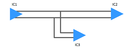
| Pin pair | Displays the difference in length between positive and negative
pin pair tracks. If the pin pair is IC1-IC2, as shown in the following figure, then the displayed difference in length is between positive pin pair and negative pin pair for IC1-IC2. |
| Differential pair | Displays the maximum difference in track length among combinations of positive and negative pin
pairs in the differential pair. In the following figure, if pin pairs are defined for IC1-IC2 and IC1-IC3, then the difference in track length IC1-IC2 is compared with the difference in track length IC1-IC3. Whichever is the greatest difference is displayed. |
- If an unrouted net is in the pin pair route, then the difference in length between positive and negative tracks is not displayed.
- If pin pairs are not defined in the differential pair, then the difference in length between positive and negative tracks is not displayed.
Displaying Pin Pair Delay
- Click the Signals button, and then click the Signals tab. A tree and a table of signals are displayed.
- Select a pin pair, or a signal that contains a pin pair (differential pair, E-net, net or bus) on the signal tree. The View field is switched to Pin pair.
- In the signal table, click the Routing tab. The Routing table contains several cells, including the Pin Pair Delay cell.
- Click the Update values button. The actual value of delay is displayed in the Pin Pair Delay cell.
- A cutting plane model of the transmission line is created from the board layer configuration.
- The delay per unit length is calculated using the 2D field solver. The delay is displayed by multiplying the delay per unit length by the track length.
- For information about via depth and the method to calculate delay, see: Calculating Via Depth and Via Delay.
- If a layer thickness is set for the resist layer, then the delay is displayed, taking the resist layer into account.
- If an unrouted net is in the pin pair route, then the delay is displayed assuming that there is a Manhattan length for a line.
- When via delay is considered, select File > Configuration > Application Settings > Advanced > Pin pair length. Select Include via depth in the Application Settings dialog, Advanced section.
Displaying the Characteristic Impedance Match Ratio of E-nets, Nets, and Pin Pairs
- Click the Signals button, and then click the Signals tab. A tree and a table of signals are displayed.
- Select an E-net, net or pin pair, or a signal that contains them (differential pair or bus) on the signal tree. The View field is switched to E-net, Net or Pin pair.
- In the signal table, click the Routing tab. The Routing table contains several cells, including the Characteristic Impedance cell.
- Set the minimum and maximum values for the characteristic impedance.
- Click the Update values button. The characteristic impedance match ratio is displayed in the Characteristic Impedance cell.
Match ratio values
| Target objects | Description |
|---|---|
| E-net | Displays the percentage (%) of track lengths that do not violate the minimum and maximum values specified for the characteristic impedance, compared to the length of all tracks that belong to an E-net. |
| Net | Displays the percentage (%) of track lengths that do not violate the minimum and maximum values specified for the characteristic impedance, compared to the length of all tracks that belong to a net. |
| Pin pair | Displays the percentage (%) of track lengths that do not violate the minimum and maximum values specified for the characteristic impedance, compared to the length of all tracks that belong to a pin pair. |
- Create a cutting plane model of a transmission line from a board layer configuration, and use a 2D field resolver to calculate the characteristic impedance.
- If a layer thickness is set for the resist layer, then the match ratio is displayed, taking the resist layer into account.
- The match ratio is not displayed if the minimum and maximum values of the characteristic impedance are not set.
Displaying the Length and Coupled Ratio of Coupled/Non-coupled Parts of a Differential Pair
- Click the Signals button, and then click the Signals tab. A tree and a table of signals are displayed.
- From the utility menu of the Constraint Browser, click Options to open the Constraint Browser Options dialog. You can specify coupling extraction options.
- Select a differential pair on the signal tree.
- In the signal table, click the Differential Report tab. The Differential Report table contains several cells, including the Differential Impedance cell.
- Click the Update values button. The coupled length, non-coupled length and coupled ratio are displayed in the Differential Impedance cell.
Value of coupled length
| Target objects | Description |
|---|---|
| Differential pair | For all route lengths that belong to a differential pair, this
displays the total value of route lengths that meet the coupling
criteria. Click Show Coupled Part in the assist menu to highlight the coupled parts in the layout tool. |
Value of non-coupled length
| Target objects | Description |
|---|---|
| Differential pair | For all route lengths that belong to a differential pair, this displays the total value of route lengths that do not meet the coupling criteria. Click Show Non-coupled Part in the assist menu to highlight the non-coupled parts in the layout tool. |
Value of coupled ratio
| Target objects | Description |
|---|---|
| Differential pair | Displays the percentage (%) of route lengths that meet the coupling criteria, in proportion to the length of all routes that belong to a differential pair. |
Displaying the Violated Length and Match Ratio for Differential Impedance
- Click the Signals button, and then click the Signals tab. A tree and a table of signals are displayed.
- From the utility menu of the Constraint Browser, click Options to open the Constraint Browser Options dialog. You can specify reference planes and coupling extraction options.
- Select a differential pair on the signal tree.
- In the signal table, click the Differential Report tab. The Differential Report table contains several cells, including the Differential Impedance cell.
- Set the minimum and maximum values for the differential impedance.
- Click the Update values button. The violated length, and match ratio for the differential impedance are displayed in the Differential Impedance cell.
Value of violated length
| Target objects | Description |
|---|---|
| Differential pair | For all route lengths that belong to a differential pair, this
displays the total value of route lengths that violate the minimum
and maximum values specified for the differential impedance. Click Show Violated Part for Differential Impedance in the assist menu to highlight the parts that violate the differential impedance in the layout tool. |
Match ratio values
| Target objects | Description |
|---|---|
| Differential pair | Displays the percentage (%) of route lengths that do not violate the minimum and maximum values specified for the differential impedance, in proportion to the length of all routes that belong to a differential pair. |
- A cutting plane model of the transmission line is created from the board layer configuration, and the differential impedance is calculated using the 2D field solver.
- If a layer thickness is set for the resist layer, then the match ratio is displayed taking the resist layer into account.
- The match ratio is not displayed if the minimum and maximum values of the differential impedance are not set.
Displaying the Violated Length and Match Ratio for Differential Pair Rule Stacks
- Click the Signals button, and then click the Signals tab. A tree and a table of signals are displayed.
- From the utility menu of the Constraint Browser, click Options to open the Constraint BrowserOptions dialog. You can specify options of differential pair rule stacks. See: Setting Constraint Browser Options.
- Select a differential pair on the signal tree.
- In the signal table, click the Differential Report tab. The Differential Report table contains several cells, including the Differential Impedance cell.
- Set a value to the differential pair rule stack.
- Click the Update values button. The violated length, and match ratio for the differential pair rule stack are displayed in the Differential Impedance cell.
Value of violated length
| Target objects | Description |
|---|---|
| Differential pair | For all route lengths that belong to a differential pair, this displays the total value of route lengths that violate the differential pair rule stack. Click Show Violated Part for Differential Pair Rule Stack in the assist menu to highlight the parts that violate the differential pair rule stack in the layout tool. |
Match ratio values
| Target objects | Description |
|---|---|
| Differential pair | Displays the percentage (%) of route lengths that do not violate the specified differential pair rule stack, in proportion to the length of all routes that belong to a differential pair. |
Displaying the Violated Length for Track Width Rules
- Click the Signals button, and then click the Signals tab. A tree and a table of signals are displayed.
- Select a net, E-net or pin pair on the signal tree.
- In the signal table, click the Routing tab. The Routing table contains several cells, including the Violated Length cell.
- Click the Update values button. The length that violates the track width rule is displayed in the Violated Length cell.
Value of violated length
| Target objects | Description |
|---|---|
| Net | The track length is displayed that violates the Normal
or Differential pair rule stack
track width rule in Track width stack.
|
| E-net | The total violated length of the nets in the E-net is displayed. |
| Pin pair | The track length is displayed that violates the Normal
or Differential pair rule stack
track width rule in Track width stack.
|
