
The Independent Source dialog allows you to add voltage and current sources to voltage supplies and signals within the schematic design. AC and DC signals can be defined. Selecting a transient function using the radio buttons displays the relevant tab. This allows you to characterize the relevant signal. A preview is automatically displayed at the bottom of the dialog. The specified values are listed in the SPICE Controller Manager, Details pane, Statement column. They are listed in the order that they are displayed in this dialog.
The Independent Source dialog is displayed by double-clicking an item in the Independent Source folder in the SPICE Controller Manager.
- Independent sources are recognized by their Reference Designator. To add a Reference Designator to a symbol, you must place a gate as a Power or Ground symbol which contains both a negative and positive signal.
- Values that you specify in this dialog must not contain spaces.
Menu
| Item | Description | |
|---|---|---|
| File | Import Waveform | Allows you to import an exported .isf text file by browsing to it in the Open dialog. The imported settings are added to the Independent Source dialog. This command is made available if a Transient Function tab is selected in this dialog. |
| Export Waveform | Allows you to export the settings in the displayed Transient Function tab as a .isf text file. This command is made available if a Transient Function tab is selected in the Independent Source dialog. | |
| Exit | Closes the Independent Source dialog. You are not prompted to save any unsaved changes. | |
| Help | Help | Launches the Online Help for the Independent Source dialog. Alternatively, press F1. |
DC/AC Tab
| Item | Description | |
|---|---|---|
| DC | Value | Specify a value for the voltage source. Enter a positive or negative value, without units. |
| AC | Amplitude | The maximum value of the AC current. This value can be positive or negative. |
| Phase | Specify the phase value for the AC current. This is the difference between the current and voltage peaks, expressed in degrees. | |
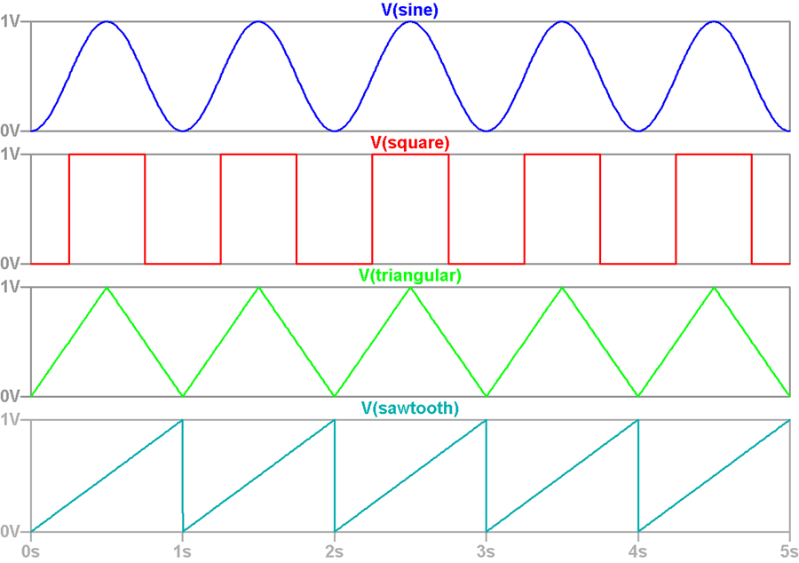
| Transient Function | Allows you to specify the characteristics of transient functions.
These show the changes in voltage and current over time, when
an input signal is applied. Examples of possible transient functions
are illustrated below.
 |
|
| Pulse | Allows you to generate square, triangular or sawtooth waveforms in the displayed PULSE tab. | |
| Sine | Allows you to generate sinusoidal waveforms in the displayed SINE tab. | |
| EXP | Allows you to generate exponential waveforms in the displayed EXP tab. | |
| PWL | Allows you to generate Piecewise linear (PWL) waveforms in the displayed PWL tab. | |
| SFFM | Allows you to generate Single Frequency FM (Frequency Modulated) waveforms in the displayed SFFM tab. | |
| None | If selected, then transient functions cannot be specified. The associated tabs are not displayed in the Independent Source dialog. |
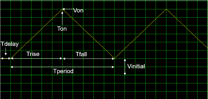
PULSE Tab
These setting are illustrated in the following preview.
| Item | Description |
|---|---|
| Vinitial | The starting voltage for the waveform. |
| Trise | The period time taken by the waveform to reach the Von value. |
| Tdelay | The period of time before the waveform starts. |
| Tperiod | The duration of the waveform, before it is repeated. |
| Von | The maximum voltage achieved. |
| Tfall | The period of time between the maximum and minimum voltages. |
| Ton | The period of time that the waveform remains at the maximum voltage. |
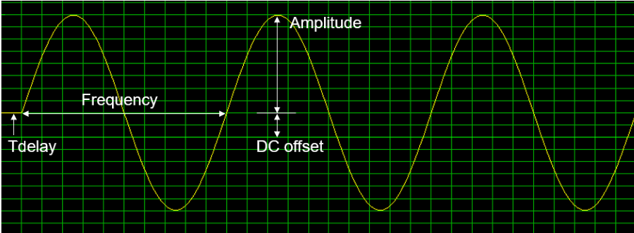
SINE Tab
Allows you to specify the characteristics of a sinusoidal waveform. These setting are illustrated in the following preview.
| Item | Description |
|---|---|
| DC offset | Specify the offset from the base current. This is the time-independent part of the output current. Enter a positive or negative value. |
| Frequency | Specify the frequency of the waveform, including units. |
| Tdelay | The length of time before the waveform starts. |
| Amplitude | The vertical distance between the sinusoidal axis and the maximum or minimum value of the function. |
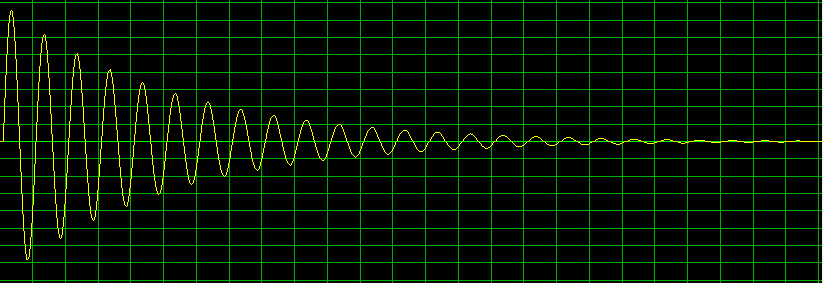
| Theta | Allows you to specify the attenuation of a signal. The amount
of attenuation is increased in proportion to the specified value.
An example is shown below of a waveform for which a Theta
value is set.
 |
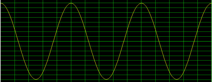
| Phi | Allows you to specify the phase shift of the signal, in degrees.
For example, the following waveform has a phase shift of 0.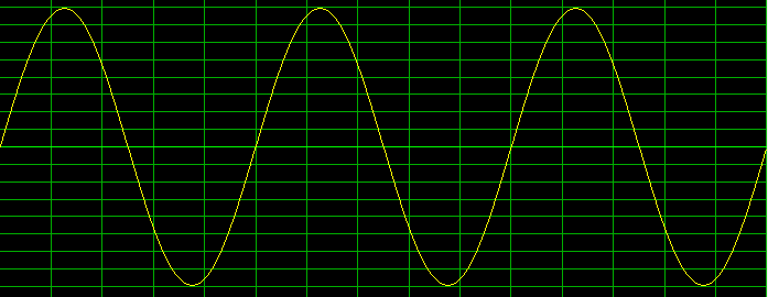 The following waveform has a phase shift of 90.
|
EXP Tab
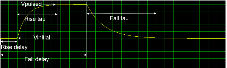
Specify the characteristics of an exponential waveform. This allows you to simulate a circuit's behavior with a specified voltage or current transient. This can be useful when working with surge stoppers or hot swap controllers. These are usually modeled using a double exponential waveform. This is characterized by a peak voltage, a rise time (usually 10%–90%), a fall time to 50% of the peak voltage, and a series resistance. These setting are illustrated in the following preview.
| Item | Description |
|---|---|
| Vinitial | The starting voltage for the waveform. |
| Rise delay | The period of time before the voltage starts to rise. |
| Rise tau | The period of time between the Vinitial and Vpulsed values. |
| Vpulsed | The peak voltage. |
| Fall delay | The total period of time before the voltage falls. This includes any Rise delay value. |
| Fall tau | The period of time taken to fall from the peak voltage to the Vinitial value. |
PWL Tab
Allows you to specify the characteristics of a Piecewise linear (PWL) waveform. These functions are used to construct a waveform from a series of straight line segments that connect specified points. The segments are drawn by linear interpolation between points that you specify. A point comprises a time value and a voltage value. Because they allow you to create custom waveforms, they are typically used to define voltage or current sources.
| Item | Description | |
|---|---|---|
| Delay | The period of time before the waveform starts. | |
| Repeat | Allows you to specify the portion of the waveform that is repeated. You can either select the point on the waveform from which it is repeated, or specify that the entire waveform is repeated. | |
| --- | A Repeat value is not set. | |
| Ever | The complete waveform is repeated. | |
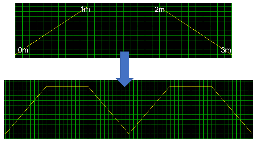
| [Time] |
Select a time that is specified in the Time current/voltage box. This defines the point on the waveform from which it is repeated. In the following example, selecting 0m in the Repeat box produces the waveform shown below. The complete waveform is repeated, beginning at 0m.
|
|
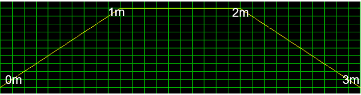
| Time current/voltage | Allows you to set the current or voltage for the times that
you specify.
Create a list of these values, using the following
format: [Time] [Current or Voltage]. For example, specifying the
following values creates the waveform show below.
0m 0
1m 1
2m 1
3m 0
 Note
|
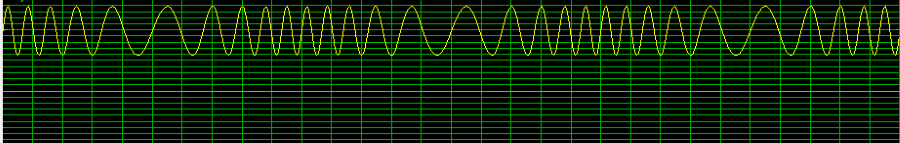
SFFM Tab
Allows you to specify the characteristics of a Single Frequency FM (Frequency Modulated) waveform. This has a single-frequency voltage source, whose frequency-modulated output voltage value is independent of the current through the source. An example of an SFFM waveform is shown below.
| Item | Description |
|---|---|
| DC Offset | The time-independent part of the output voltage. |
| Carrier frequency | The frequency of the carrier wave. This may be zero, but cannot be negative. |
| Modulation index | The amount by which the modulated signal varies around its unmodulated level. It can be zero, but cannot be negative. |
| Amplitude | The magnitude of the sinusoidal part of the output voltage. |
| Signal frequency | The frequency of the modulated signal. This value must be greater than or equal to zero. |
Preview
If a Transient Function value is selected in the DC/AC tab, then the Preview pane is displayed at the bottom of the Independent Source dialog. A preview of the transient function is automatically displayed when you enter values in the associated Transient Function tab. The scale of the Preview pane is automatically adjusted to accommodate the specified values. When you click Apply, the previewed waveform is colored yellow.
| Item | Description |
|---|---|
| OK | Saves the settings in the Independent Source dialog, and closes it. |
| Cancel | Closes the Independent Source dialog without saving any unsaved changes. |
| Apply | Saves the settings in the Independent Source dialog. The dialog remains open. Any transient waveforms are colored yellow in the Preview pane. |
