
The Edit Parameters dialog allows you to configure, import and save the parameters for importing an IDX file. It is displayed by clicking Edit parameters in the Import (IDX) dialog. The object types shown below can be imported from an IDX file that is output from the following mechanical CAD packages.
- Creo version 3.0 and version 4.0 (PTC)
- NX version 12.0 (Siemens PLM)
| Object type | Creo version 3.0 and version 4.0 (PTC) | NX version 12.0 (Siemens PLM) |
|---|---|---|
| Board Outline | Supported | Supported |
| Hole | Supported | Supported |
| Non-circular hole | Not Supported | Supported |
| Component | Supported | Supported |
| Area | Supported | Supported |
| Other layers | Not Supported | Not Supported |
Conversion Objects
An IDX file is in XML format, and consists of the Header, Body and ProcessInstruction sections. The shape and attributes of each object are described in the Body section. The following objects in the IDX Body section are converted when the file is imported to eCADSTAR PCB Editor.
| IDX Object | Description | Conversion process | ||||||
|---|---|---|---|---|---|---|---|---|
| UnitLength | Unit | Converts the value of each numeric value in the described unit. | ||||||
| Item | Indicates an object on the board. | Converts to the target eCADSTAR object, depending on the type of object referenced by each item. | ||||||
| Stratum | Indicates a layer. | Converts to the board outline. However, when Stratum has the StratumTechnology description, the object is converted to the layer that matches the StratumTechnology attribute. | ||||||
| InterStratumFeature | Indicates a hole. | Converts to hole data. However, holes related to the component are excluded from the target. | ||||||
| AssemblyComponent | Indicates a component. | For a component assigned to the item that references AssemblyComponent, the reference name is used as a key when the component is moved. | ||||||
| KeepOut | Indicates a keepout area. | Converts to a component keepout, track keepout or via keepout area, depending on the value of the Purpose attribute. | ||||||
| KeepIn | Indicates a limit area. | Converts to a height limit area, placement area or routing area, depending on the value of the Purpose attribute. | ||||||
| Bend | Bend information | Converts to a bend line or bend area. | ||||||
| FunctionalItemShape | Indicates an area that has a function. | When the FunctionalItemShape attribute
is set using one of the following values, it is converted to the
target object. If another attribute is set, then it is not converted.
|
||||||
| StratumTechnology | Layer technology | The target object is converted to the layer for which TechnologyType is set to Design, and also the LayerPurpose and LayerPositionType attributes match the attributes specified in the Other Layers section. | ||||||
| ShapeElement | Indicates a shape | Converts to a 2D shape. Shapes for which the Inverted attribute is set to true are converted to cutouts. | ||||||
| System | Indicates a system. | The item owner is defined by referencing the system name, with the attribute defined in SystemScope of InstanceName set to each item. | ||||||
| CartesianPoint | Indicates a point. | Converts to 2D coordinates. | ||||||
| Line | Indicates a line. | Converts to a line. | ||||||
| PolyLine | Indicates a polyline. | Converts to a continuous line. | ||||||
| Arc | Indicates an arc. | Converts to an arc. | ||||||
| CircleCenter | Indicates a circle by the center point and radius. | Converts to a circle. | ||||||
| Circle3Point | Indicates a circle by three points on the circumference. | Converts to a circle. | ||||||
| Elllipse | Indicates an ellipse. | Converts to an approximated segment array. | ||||||
| CurveSet2d | Indicates a 2D shape, including its the upper limit and lower limit. | Converts to a 2D shape, including its the upper limit and lower limit. |
The following objects are not converted.
| IDX Object |
|---|
| RoleInOrganisation |
| RoleOnItem |
| RoleOnItemInstance |
| NonFeatureItemShape |
| SimpleText |
| UnitPower |
| ExternalGeometricModel |
| UnitWork |
| ExternalSource |
| GeneralClassification |
| UnitCapacitance |
| Hyperbola |
| Annotation |
| UnitResistance |
| ItemConstraint |
| Material |
| OffsetCurve |
| Organisation |
| Parabola |
| Person |
| PointOnCurveIntersection |
| PointOnCurveDistance |
| BSplineCurve |
| TrimmedCurve |
| CompositeCurve |
| History |
| HistoryEntry |
| AngleLength |
| UnitSurface |
| UnitVolume |
| UnitWeight |
| UnitAmperage |
| UnitVoltage |
| MasterPart |
The fields in this dialog are described below.
| Item | Description | |||||||||||||||||||||||||
|---|---|---|---|---|---|---|---|---|---|---|---|---|---|---|---|---|---|---|---|---|---|---|---|---|---|---|
| Import | If available, this option could allow you to import changes that are specified in the IDX file. | |||||||||||||||||||||||||
| Only import baseline items |
|
|||||||||||||||||||||||||
| Board outline | Allows you to specify whether the board outline is imported.
You can also specify whether an area fill that has the same shape
as the board outline is generated, and whether a value for the
board size is imported. Area fills and cutouts defined in the
board outline are input to the board outline layer. If there are
multiple board outline shapes, then they are all imported. It
is recommended that board outlines that are not required are deleted
after the IDX file is imported. The following information is also
imported.
|
|||||||||||||||||||||||||
| Import board outline |
|
|||||||||||||||||||||||||
| Generate layout area |
|
|||||||||||||||||||||||||
| Import board size |
|
|||||||||||||||||||||||||
| Hole | Allows you to specify whether holes are imported. You can also
specify how padstacks and non-circular holes are converted. A
hole is converted to a round hole or slot hole,
depending on its shape. The converted data is input to the hole
layer. If the conditions are satisfied for a registered padstack
and hole shape, then the object is converted to a padstack. Non-circular
holes are imported to a non-circular hole layer, and are not converted
to round holes or slot holes. The pen width,
filled width and filled angle are set to 0.0.
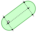
Round Holes If cutouts are composed of one or multiple concentric arcs,
then they are converted to round holes, as shown below. Slot Holes When the following conditions are met, cutouts are converted to slot holes. This is illustrated below.
Depending on the type that is specified in the IDX file for InterStratumFeatureType, the plating attribute of the hole is set as shown below.
|
|||||||||||||||||||||||||
| Import hole |
|
|||||||||||||||||||||||||
| Convert non-plated hole to hole |
|
|||||||||||||||||||||||||
| Hole diameter tolerance | When assigning a padstack, specify the tolerance that is allowed for the diameter of the hole. | |||||||||||||||||||||||||
| Padstack table | Allows you to specify the padstacks to be converted. Right-click
in the table and select Add Rows
on the assist menu to display the Select
Padstack dialog. Select a padstack in this dialog by clicking
it. Multiple padstacks can be selected using the Ctrl
or Shift keys, or by dragging
the cursor. To delete a row, right-click in the table and select
Delete Rows on the assist menu.
You can select multiple rows to delete by clicking them using
the Ctrl or Shift
key, or by dragging the mouse.
|
|||||||||||||||||||||||||
| Convert undefined hole |
|
|||||||||||||||||||||||||
| Convert non-circular hole |
|
|||||||||||||||||||||||||
| Component | Allows you to specify whether placement information for an
imported component is automatically modified, and whether placement
information is modified for fixed components. Each component is
identified using a reference as a key. Depending on the IDX attributes,
the following operations are performed.
|
|||||||||||||||||||||||||
| Change placement information |
|
|||||||||||||||||||||||||
| Update attributes on fixed components |
|
|||||||||||||||||||||||||
| Area | The Area table allows you to specify the layers that are converted to area data. Right-click in the table and select Add Rows on the assist menu to display the Select Layer dialog. Select the required layers in this dialog. To delete a row, right-click in the table and select Delete Rows on the assist menu. You can select multiple rows to delete by dragging the mouse, or by clicking them using the Ctrl or Shift key. The shape of KeepIn and KeepOut objects in the IDX file is converted. If the eCADSTAR height limit area layer is selected as the input destination, then the upper limit of the area is input as the height. If another layer is specified, then height information is not set for the area. | |||||||||||||||||||||||||
| eCADSTAR Layer name | Displays the layers that you select in the Select
Layer dialog. To change a selected value, point the cursor
in this field and then click the displayed  button. The Select Layer
dialog is displayed.
button. The Select Layer
dialog is displayed. |
|||||||||||||||||||||||||
| Import |
|
|||||||||||||||||||||||||
| IDX: Area type | Specify the area type that is imported for each eCADSTAR layer. The options that
you can select vary depending on the type of layer in the eCADSTAR Layer name column.
|
|||||||||||||||||||||||||
| IDX: Placement side | If applicable, select the required placement side. The following
options can be selected.
|
|||||||||||||||||||||||||
| UserArea | A user area is a user-arbitrarily named area on the board that does not have any specific purpose such as restriction. The UserArea table allows you to specify the layers that are converted to user area data. Right-click in the table and select Add Rows on the assist menu to display the Select Layer dialog. Select the required layers in this dialog. To delete a row, right-click in the table and select Delete Rows on the assist menu. You can select multiple rows to delete by dragging the mouse, or by clicking them using the Ctrl or Shift key. | |||||||||||||||||||||||||
| Specify placement side |
|
|||||||||||||||||||||||||
| eCADSTAR Layer name | Displays the layers that you select in the Select
Layer dialog. To change a selected value, point the cursor
in this field and then click the displayed
button. The Select Layer
dialog is displayed. |
|||||||||||||||||||||||||
| Import |
|
|||||||||||||||||||||||||
| IDX: Name | Specify the name of the User Area. | |||||||||||||||||||||||||
| IDX: Placement side | Select the required placement side. The following
options can be selected.
When Specify placement side is not selected, the placement side is not referenced. |
|||||||||||||||||||||||||
| Other Layers | Allows you to specify the details of any additional layers
that are imported. A polyline with no area fill or width is input
to the specified layer. The pen width, filled width and filled
angle of the area fill are set to 0.0. If the following layers
are specified as the input destination, then a polyine is not
input.
|
|||||||||||||||||||||||||
| Other layers to output | This table allows you to specify any additional layers to import from the IDX file. Right-click in the table and select Add Rows on the assist menu to display the Select Layer dialog. Select the required layers in this dialog. To delete a row, right-click in the table and select Delete Rows on the assist menu. You can select multiple rows to delete by dragging the mouse, or by clicking them using the Ctrl or Shift key. | |||||||||||||||||||||||||
| eCADSTAR Layer name | Displays the eCADSTAR
layers that you select in the Select
Layer dialog. To change a selected value, point the cursor
in this field and then click the displayed
button. The Select Layer
dialog is displayed. |
|||||||||||||||||||||||||
| Import |
|
|||||||||||||||||||||||||
| IDX: Layer purpose | Specify the purpose of each imported layer. The available options
vary depending on the type of layer in the eCADSTAR Layer
name column.
|
|||||||||||||||||||||||||
| IDX: Layer position type | Specify the layer position. The following options can be selected.
|
|||||||||||||||||||||||||
| Existing layer data |
|

In eCADSTAR, a track keepout area restricts the use of any surface mount conductor object. This includes the following objects.
- Pad/Padstacks
- Route/Line
- Area
- Text
