Mechanical Object Organizer (Align PCB)
By providing extract reference coordinates from the board
and mechanical data, the board can be moved to the position specified
by the coordinates. The coordinates used for the alignment are called
a Reference point. This holds the X,
Y, and Z coordinates, and position information. Reference points are automatically
extracted by Mechanical Object Organizer.
The reference points of board data, as well as those of mechanical data
must be selected. Alignment is carried out by matching these reference
points.
Types of reference points
The following information is extracted from the model,
and displayed on the canvas.
| Icon |
Reference point type |
Description |

|
Axis |
The coordinate system held by each selected model, and displayed
at the local origin. For mechanical items, coordinate systems
that have been inserted at arbitrary coordinates as WCS are also
displayed as coordinate systems. |

|
Vertex |
Represents a vertex. |

|
Center point of arc |
Represents the center point of a circle or arc.
When extracting an object from mechanical data, the center point
is not displayed. Most of the edges in mechanical data are entered
as splines (internally the spline curves of the NURBS type). If
the shape is slightly distorted, then the center point cannot
be calculated. |

|
Center point of polygon |
Displays selection candidates of the reference points at the
center position, extracted from vertex coordinates of a polygon.
A slot hole is assumed (Candidates are also
displayed for a polygon that is completely different from this
hole). However, the bulge of an arc or spline is not considered when calculating
the center point. |

|
Point of bounding box |
Represents the vertices of a bounding box (total: eight vertices). |

|
Center point of bounding box |
Represents the center point of a bounding box (one point),
and the center points of area fills (six points) that constitute
the bounding box (total: seven points). |
Display of reference points
Extracted reference points are displayed in the following
ways:
- The contents of reference points vary depending
on the status. When a model is selected, and candidates of reference
points extracted from the model are displayed, the points are displayed.
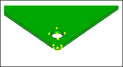
- When you select a single reference point from two
or more candidates, the following items are displayed: the coordinate
axis (blue) indicating the Z-axis direction, a disk (gray) representing
the X-Y plane, and an anchor indicating the X-axis direction. Clicking
the selected reference point again selects another reference point
at the same coordinates. If there are no other reference points at
the same coordinates, this cancels the selection of the reference
point.
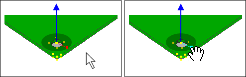
- The reference point can be rotated around the Z-axis
by pressing and dragging an anchor.
While dragging the anchor, the mouse cursor is snapped to another candidate.
The anchor stays at the position where the mouse cursor is released.
The anchor can be moved by pressing and dragging it again. If candidates
are closely spaced at the release position, you can first release
the anchor at an appropriate position, zoom in the circumference of
the release position, and then press and drag the anchor again to
the correct position.

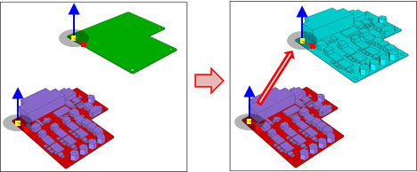
- Selecting reference points of PCB and mechanical
item displays them in preview mode. The preview mode can be turned
ON or OFF by toggling.
Command dialog
Reference point of PCB
Reference point
| Item |
Description |
| Coordinates
|
Displays the coordinates and icon of the reference point selected
on the canvas. If a new reference point is selected, the contents
are updated.
- The attributes of the reference point cannot be changed
in this stage.
- The reference point has a view filter as an optional parameter.
Click [+] on the left side of the label to expand options
and configure view settings in the dialog.
|
Coordinate system
| Value |
Description |
| ON
|
Displays the reference point of the coordinate system type. |
| OFF
|
Does not display the reference point of the coordinate system
type. |
Bounding box
| Value |
Description |
| ON
|
Displays the reference points of the vertex type, and the center
point type of a bounding box. |
| OFF
|
Does not display the reference points of the vertex type, and
the center point type of a bounding box. |
Center point of polygon
| Value |
Description |
| ON
|
Displays the reference point of the center point type of a
polygon. |
| OFF
|
Does not display the reference point of the center point type
of a polygon. |
Center point of arc
| Value |
Description |
| ON
|
Displays the reference point of the center point type of an
arc. |
| OFF
|
Does not display the reference point of the center point type
of an arc. |
Vertices
| Value |
Description |
| ON
|
Displays the reference point of the vertex type. |
| OFF
|
Does not display the reference point of the vertex type. |
Reference point of destination
| Value |
Description |
| Reference point
|
Same as Reference point of PCB. |
| Optional parameter
|
Same as Reference point of PCB. |
| Reverse
|
Reverses the coordinate axis of a selected reference point.
The directions of all vectors are reversed in the X-axis, Y-axis,
and Z-axis. |
Preview
Show preview
| Value |
Description |
| ON
|
Turns ON the preview mode. |
| OFF
|
Turns OFF the preview mode.
You can turn OFF preview mode if it hinders your reference point
settings. |
View mode
| Value |
Description |
| Wireframe
|
Displays edges only. An "Edge" is a boundary between
area fills. |
| Shading
|
Displays edges and area fills. The area fills are shaded, depending
on the angle of view. |
| Item |
Description |
|
|
Aligns the position. The board is moved to the position where
you want to match the reference points in the board and mechanical
item. |
|
|
Cancels the position alignment, and closes the dialog. The
currently-displayed preview disappears. |
Assist menu
The following assist menu items can be selected by right-clicking
the mouse.
| Item |
Description |
|
|
Aligns the position. The board is moved to the position where
you want to match the reference points in the board and mechanical
item. |
| Reverse
|
Reverses the coordinate axis of a selected reference point.
The directions of all vectors are reversed in the X-axis, Y-axis,
and Z-axis. |
| Undo
|
Reverts the changes that you make to the board. |
|
|
Cancels the position alignment, and closes the dialog. The
currently-displayed preview disappears. |

