| Item |
|
Description |
| Import parameters
|
Using
the Open dialog, you can load the parameters that are stored in a .xml file. |
| Export parameters
|
The parameters that you configure in this dialog can be saved
to a .xml file using the Save As dialog. |
| Layer mapping
|
- Set the association between layers in the
design and the DXF layers.
- To add a combination of layers, select
, , or on the assist menu.
- If is selected, all layers displayed in the
Select Layer dialog
are added.
- If is selected, layers are added for which Visible
layer is set to ON
in Layer View on the
Layer Settings panel.
- Then, enter DXF
layer name corresponding to the specified Layer name.
- To not change the orientation of the layer, set Mirror
to None.
Note
Output from one layer to multiple DXF layers
is not possible.
|
| |
Layer to convert
|
Allows you to specify how layers are converted when exported
to a DXF file. |
| |
|
| Item |
|
Description |
| DXF layer name
|
|
Define the layer name in the DXF file. Besides specifying
layers on the Layer mapping
page, you can create DXF layers using the following functions:
- Output reference name.
- Output negative figures for a conductor
layer. These are exported to a new DXF layer, as specified
in the Layer name
column, using the following rule: "%Layer name%_nega".
- The following types of figure are
exported:
- Clearance land.
- Thermal land.
- Meshes in mesh planes.
|
| Layer name
|
|
In the displayed Select Layer dialog, select the layer name in the design. This dialog is launched by pointing the cursor in this column, and clicking the displayed  button. button. |
| Color
|
|
Allows you to specify the color of each exported layer
by specifying a color number or color name, or by selecting
a color in the
Select DXF Color dialog. If you do not specify a value, the DXF color number
is used that is closest to the RGB value of the layer
color.
- To specify a color number, enter
an integer between 1 and 255 and press Return
on the keyboard. The specified number is displayed
in the cell, and the cell is filled using the corresponding
color.
- The specify a color name, enter
it in the cell, and press Return
on the keyboard. The specified name is displayed,
and the cell is filled using the corresponding color.
You can enter one of the following values. These are
displayed in the first row of the Select DXF Color dialog, as shown below.
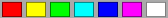
- red
- yellow
- green
- cyan
- blue
- magenta
- white
- To select a color from the palette,
point the cursor at the relevant cell in the Color column, and then
click the displayed "..."
button. The
Select DXF Color dialog is displayed. Select a color in the dialog
and click OK. The color
name or color number is displayed, and the cell is
filled using the corresponding color.
- The first row of the palette displays
the following colors. The corresponding color names
and color numbers are also shown below.

- red
- yellow
- green
- cyan
- blue
- magenta
- white
- 8
- 9
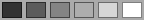
- The last row of the palette displays
the shades of gray, as shown below.
Note
If the exported DXF file is subsequently
imported into eCADSTAR, the colors that you specify are
not used. This is because these settings are overruled
by the layer color settings in eCADSTAR. However,
they may be used by other drawing packages. |
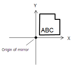
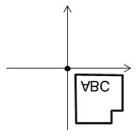
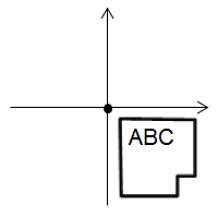
| Mirror
|
None
|
The layer that is specified in the Layer
name column is exported without being changed.
For example:
 |
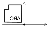
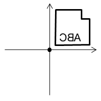
| X
|
The layer is mirrored in the X direction when exported.
For example:
 |
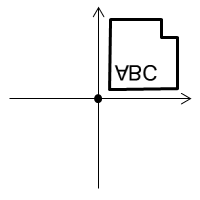
| Y
|
The layer is mirrored in the Y direction when exported.
For example:
 |
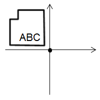
| Only char. in X
|
Only characters are mirrored in the X direction when
the layer is exported. For example:
 |
| Only char. in Y
|
Only characters are mirrored in the Y direction when
the layer is exported. For example:
 |
| Exclude char. in X
|
All objects except characters are mirrored in the X
direction when the layer is exported. For example:
 |
| Exclude char. in Y
|
All objects except characters are mirrored in the Y
direction when the layer is exported. For example:
|
|
| |
|
The following items, specific to the Layer
to convert box, are available by right-clicking in the
Layer to convert box.
| Item | Description |
|---|
| Adds rows for all layers to the Layer
to convert box. | | Adds rows for all visible layers to the Layer
to convert box. | | Displays the Select
Layer dialog. This dialog allows you to select the
layers to be added to the Layer to
convert box. You can select board layers, conductor
layers, non-conductor layers and user-defined layers. | | Deletes all selected rows from the Layer
to convert box. |
|
| |

|
Moves the row that is selected in the Layer
to convert box to the Layer
not to convert box. Select
multiple rows using the CTRL or
Shift keys, or by dragging the cursor. |
| |

|
Moves the row that is selected in the Layer
not to convert box to the Layer to convert box. Select multiple
rows using the CTRL or Shift
keys. |
| |
Layer not to convert
|
The Layer not to convert box allows you to save the settings in
the Layer to convert box.
- The values in the Layer
not to convert box are
read-only.
- Only the settings specified in the Layer to convert box are referenced
during the export process.
| Item | Description |
|---|
| DXF layer name | The layer name that you define for the DXF file in
the Layer to convert
table. | | Layer name | The layer name in the design that you select in the
Layer to convert table. | | Color | Displays the color number or color name that is associated
with the relevant layer. | | Mirror | The setting that you specify in the Mirror
column in the Layer to convert
table. |
|
| Export
|
|
Allows you to configure the data that is exported to a DXF
file. |
| |
Version
|
Specify the version of the exported DXF file. If R12
is selected, the following are made unavailable to ensure compatibility
with DXF specifications:
- Font name
- Output hatching of area fill
- Output hatching of polyline
| Item | | Description |
|---|
| DXF file version | R12 | The version of the exported DXF file is Release 12. | | R14 | The version of the exported DXF file is Release 14. |
|
| |
Unit
|
| Item |
|
Description |
| DXF file unit
|
mm
|
Values are exported in millimeters. |
| inch
|
Values are exported in inches. |
| micron
|
Values are exported in microns. |
| mil
|
Values are exported in mils. |
|
| |
Character
|
| Item |
|
Description |
| Output character
|
Selected |
Characters are exported as DXF characters. |
| Not selected |
Characters are exported as figures. |
| Font name
|
Single-byte
|
Specify the single-byte font name that is exported
(default: "txt"). |
| |
Multibyte
|
Specify the multibyte font name that is exported (default:
"EXTFONT"). |
|
| |
Conversion figure
|
| Item |
|
Description |
| Scale
|
|
Set a scale parameter between 0.01 and 100.0 to reduce or enlarge a figure that is exported to the DXF file.
- A value of 0.5 reduces the size
by half.
- A value of 2.0 makes it twice as
large.
|
| Conversion
mode
|
Segment/Arc/Circle
|
Figures are divided into segments, arcs and circles
before they are exported. For areas, area fills, polylines
and other figures composed of multiple lines, each line
is divided and exported individually. If selected, then
the Centerline with width
option in the Polyline
conversion mode box is made unavailable. |
| Polyline
|
Figures are exported as polylines. Areas, area fills,
polylines and other figures, which are composed of multiple
lines, are exported in their original structures. If selected,
the following check boxes are made available:
- Output
hatching of area fill
- Output
hatching of polyline (only made available if
Outline is selected
in the Polyline conversion mode field.
|
| Polyline conversion
mode
|
Outline
|
Shapes of the outlines are exported where the pen width
of areas, area fills and polylines is divided. The Output hatching of polyline
fields are made available. |
| Centerline
|
Shapes of the centerlines of areas, area fills and
polylines are exported, and the pen width is ignored. |
| Centerline with width
|
Shapes of the centerlines of areas, area fills and
polylines, and their pen width attributes are exported.
If selected, then the Segment/Arc/Circle
option in the Conversion
mode box is made unavailable. |
| Output hatching
of area fill
|
Selected |
Shapes of area fills are exported as hatches. If selected,
the following check boxes are made available:
|
| Not selected |
Hatches of area fills are not exported. |
| Pattern
|
Diagonal
|
The hatch pattern for area fills is set to ANSI31. |
| Fill
|
The hatch pattern for area fills is set to SOLID. |
| Pitch
|
|
Set a positive value for the pitch of hatches for area
fills. |
| Output hatching
of polyline
|
Selected |
Shapes of polylines are exported as hatches. When Polyline conversion mode is
set to Outline, the
areas inside the outlines are hatched. If selected, the
following check boxes are made available:
|
| Not selected |
Hatches of polylines are not exported. |
| Pattern
|
Diagonal
|
The hatch pattern for polylines is set to ANSI31. |
| Fill
|
The hatch pattern for polylines is set to SOLID. |
| Pitch
|
|
Set a positive value for the pitch of hatches for polylines. |
|
| |
Mirror
|
| Item |
|
Description |
| Origin of mirror
|
|
Set the base point that is referenced by the mirror
process in the Layer mapping
page and the Output reference
name field. |
| |
X |
The X coordinate of the base point that is referenced
by the mirror process. |
| |
Y |
The Y coordinate of the base point that is referenced
by the mirror process. |
|
| OK
|
|
Saves the values that you set in the Edit
Parameters dialog and closes the dialog. |
| Cancel
|
|
Closes the Edit Parameters dialog
without saving your settings. |

