
The Parametric Generation (BGA/PGA) dialog allows you to generate shapes for BGA/PGA components. It is displayed by selecting Home > Generate >Parametric >BGA/PGA on the Footprint Editor ribbon. This command is only available in 2D View mode.
Pin Shape Tab
Symbol Mark Tab
Component Area Tab
Pin Shape Tab
Allows you to specify the configuration of the pins for a BGA/PGA component.
Placement
| Parameter | Value | Description |
|---|---|---|
| Pattern | Grid | Specifies that the pins are arranged in a regular grid pattern,
as shown below. The dimensions shown on the image refer to the
values in the Pin count settings
table.
|
| Staggered | Specifies that the pins are arranged in a staggered pattern,
as shown below. The dimensions shown on the image refer to the
values in the Pin count settings
table.
|
|
| Exception pin | Selected | Specifies that there are exception pins in the layout. Exception pins are specified in the Pin count m1, Pin count m2, Pin count n1, and Pin count n2 boxes. |
| Not selected | Specifies that there are no exception pins in the layout. All pins in the "m" and "n" directions are used. |
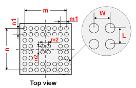
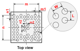
Pin count settings
| Parameter | Value | Description |
|---|---|---|
| Pin count m | Integer equal to, or greater than 1. | Specify the pin count in the direction of the X-axis. |
| Pin count m1 | Integer equal to, or greater than 1. | Specify the number of columns in the outer area in the direction of the X-axis. This field is only available when Exception pin is selected. |
| Pin count m2 | Integer equal to, or greater than 1. | Specify the number of columns in the center area in the direction of the X-axis. This field is only available when Exception pin is selected. |
| Pin count n | Integer equal to, or greater than 1. | Specify the pin count in the direction of the Y-axis. |
| Pin count n1 | Integer equal to, or greater than 1. | Specify the number of rows in the outer area in the direction of the Y-axis. This field is only available when Exception pin is selected. |
| Pin count n2 | Integer equal to, or greater than 1. | Specify the number of rows in the center area in the direction of the Y-axis. This field is only available when Exception pin is selected. |
| Pin pitch W | Real number equal to, or greater than 0. | Specify the pin-out pitch in the direction of the X-axis. |
| Pin pitch L | Real number equal to, or greater than 0. | Specify the pin-out pitch in the direction of the Y-axis. |
The unused pin area can be determined by examining the difference between the values for m1 and m2 and between those for n1 and n2. As the diagram on the dialog shows, this will be a 'frame' around the central, used pin area.
Number of pins
| Value | Description |
|---|---|
| Integer | The number of used pins in the BGA/PGA. This value is calculated using the Pin count m and Pin count n values. |
Padstack Name
| Value | Description |
|---|---|
| String | Allows you to select the padstack that is used for the pin shape. |
Position
| Value | Description |
|---|---|
| Center | The origin is set as the center. |
| Lower left | The origin is set as the lower left. |
| Upper left | The origin is set as the upper left. |
| Upper right | The origin is set as the upper right. |
| Lower right | The origin is set as the lower right. |
Symbol Mark Tab
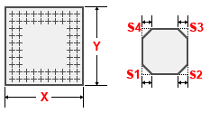
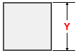
Allows you to generate a symbol mark for a BGA/PGA component, as shown below. The dimensions shown on the image refer to the values in the Symbol mark shape settings table.
Generate symbol mark
| Value | Description |
|---|---|
| Selected | Allows you to generate a symbol mark shape. The relevant fields in the Symbol Mark tab are made available. |
| Not selected | Specifies that a symbol mark shape is not generated. All fields in the Symbol Mark tab are made unavailable. |
Symbol mark shape settings
The following settings are only made available if Generate symbol mark is selected.
| Parameter | Value | Description |
|---|---|---|
| Symbol length X | Real number greater than 0. | Specify the length of the symbol mark shape in the direction of the X-axis. |
| Symbol length Y | Real number greater than 0. | Specify the length of the symbol mark shape in the direction of the Y-axis. |
| Chamfer S1 | Real number equal to, or greater than 0. | Specify the chamfer length at the lower-left corner of a symbol mark shape. |
| Chamfer S2 | Real number equal to, or greater than 0. | Specify the chamfer length at the lower-right corner of a symbol mark shape. |
| Chamfer S3 | Real number equal to, or greater than 0. | Specify the chamfer length at the upper-right corner of a symbol mark shape. |
| Chamfer S4 | Real number equal to, or greater than 0. | Specify the chamfer length at the upper-left corner of a symbol mark shape. |
The value specified for chamfer is the length of the hypotenuse of a right-angled triangle.
Object
The following settings are only made available if Generate symbol mark is selected.
Object
| Parameter | Description |
|---|---|
| Line | A symbol mark shape is generated with lines. If Line is selected, the Line width and Line type boxes are made available. |
| Area fill | A symbol mark shape is generated with an area fill. If Area fill is selected, the Pen width box is made available. |
Line width
| Value | Description |
|---|---|
| Real number greater than 0. | Specify the width of the line. This field is only available when Line is selected. |
Line attributes
The following setting is only made available if Generate symbol mark is selected, and Line is selected in the Object group.
Line type
Specify the format of the line.
| Value | Description |
|---|---|
| Solid | A solid line is generated. |
| Dash | A dash line is generated. |
| Dash dot | A dash-dot line is generated. |
| Dash dot dot | A dash-dot-dot line is generated. |
Area fill attributes
The following settings are only made available if Generate symbol mark is selected, and Area fill is selected in the Object group.
Pen width
| Value | Description |
|---|---|
| Real number equal to or greater than 0. | Set the pen width of the area fill to be generated |
Generation layer
| Value | Description |
|---|---|
| Layer name |
|
Component Area Tab
Allows you to generate a component area for the BGA/PGA component.
Generate component area
| Value | Description |
|---|---|
| Selected | Allows you to generate a component area. All fields in the Component Area tab are made available. |
| Not selected | Specifies that a component area is not generated. All fields in the Component Area tab are made unavailable. |
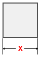
Length X
The following setting is only made available if Generate component area is selected.
| Value | Description |
|---|---|
| Real number greater than 0. | For a rectangular component area, this setting specifies the
X value of its dimensions.
|
Length Y
The following setting is only made available if Generate component area is selected.
| Value | Description |
|---|---|
| Real number greater than 0. | For a rectangular component area, this setting specifies the
Y value of its dimensions.
|
Height (Standoff - Maximum)
The following setting is only made available if Generate component area is selected.
| Value | Description |
|---|---|
| Real number equal to, or greater than 0. | Specify the spatial height of the component area. |
Generation layer
The following setting is only made available if Generate component area is selected.
| Value | Description |
|---|---|
| Layer name |
|
