
The Auto Placement
command allows you to automatically place components in a component group
area. To display the Auto Placement
dialog, select Component > Placement >
 Auto Placement on the eCADSTAR PCB Editor
ribbon. For a component that is outside of the component area, double-clicking
it will execute the command. Alternatively, right-click it and choose
Selection End on the assist menu. You can also select a component by dragging the cursor
over it. It is placed when you release the mouse button. You can select
multiple components using the CTRL
key or by dragging the cursor over them.
Auto Placement on the eCADSTAR PCB Editor
ribbon. For a component that is outside of the component area, double-clicking
it will execute the command. Alternatively, right-click it and choose
Selection End on the assist menu. You can also select a component by dragging the cursor
over it. It is placed when you release the mouse button. You can select
multiple components using the CTRL
key or by dragging the cursor over them.
Components are placed in the most appropriate location by taking their net connections into account, and by minimizing the net length. Components with the largest component area are placed first. Smaller components are then placed around these components and are aligned by centre point.
To place components, select them on the canvas or by using the Component Selector, and then click Selection End on the assist menu. Alternatively, double-click a component on the canvas. By default, components are placed on Side-A. If this is not possible, then they are placed on Side-B. While the command is running, components that are placed on Side-A are shown in red, and components that are placed on Side-B are shown in green. If components cannot be placed, then the Reference dialog is displayed after the command finishes. These components are listed in the dialog, and are moved to the outside of the board, at the bottom-right.
If you specify Height Limit Area, Rule Area or DRC constraints in the component area, then these are obeyed by the command. If a component cannot be moved into a component area without violating a constraint, then it is moved to the bottom-right corner of the component area. If a component is a member of a Component group, then it is automatically placed in the relevant group on the canvas. Components that are not members of Component groups may also be placed in a component group. If no component group exist, then components are placed within the layout area.
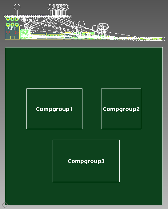
In the following example, three component groups have been added to the component area, and all components are outside of this area.
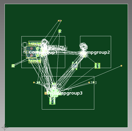
If you execute the Auto Placement command and select the components, then they are placed in the component area. Components that are in a component group are moved into the relevant position on the canvas. Components that are not in a component group are placed in an appropriate position in the component area, or in an appropriate component group. The command distributes components equally on the board, if possible, and recognizes rule areas and keepout areas.
Pack Tight
| Value | Description |
|---|---|
| ON | If selected, and the specified components are in a component
group, then they are arranged densely around the one with the
maximum component area. This is illustrated in the following example.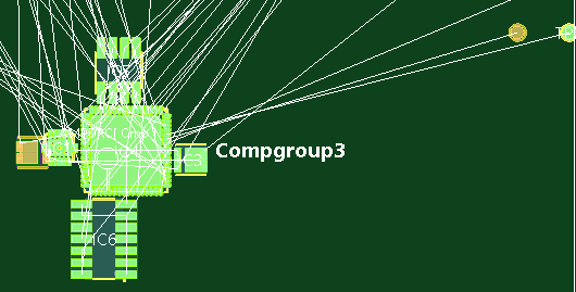
|
| OFF |
If selected, and the specified components are in a component
group, then they are distributed within the component group. This
is illustrated in the following example.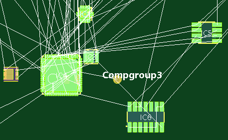
|
- To abort the Auto Placement command while it is running, press Ctrl + Break on the keyboard.
- As you cannot place components on inner layers, the active layer is automatically changed to Conductor-1 when you execute this command.
- If variant components are included within a selection, then only one of the variants is placed by the Auto Placement command. Note that a license is required to access the variation functionality in eCADSTAR.
- If multiple component groups exist for a component, then only one of them is used exclusively and the others are ignored. For example, if there are component groups for Side-A and Side-B, then only the component group for Side-A is used.
- The following components are not valid for placement using the Auto Placement command, and are not moved.
- Components that you set to Fix by right-clicking them on the canvas, and selecting Fix. When a component is set to Fix, the Fixed field in the Properties Panel is set to NO.
- Non-electrical components.
- Components that contain no nets.
- Components that contain no pins.
- Unplaced components. A component is set as "Unplaced" by right-clicking it on the canvas, and selecting Unplaced on the assist menu. The component is removed from the design.
