
The Move Track command allows you to move a routed segment while pushing away obstacles. Vias can also be moved using this command. Launch this command by clicking Net /Route > Routing > Move Track on the ribbon in eCADSTAR PCB Editor.
Note
- If you move a via using the Move Track command, then the segment that is connected to the via is also moved.
- You can specify that stacked vias are moved as a single object.
- If you select the vertex between two segments, then both segments are moved.
Command dialog
Move Stacked vias
| Value | Description |
|---|---|
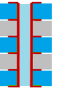
| ON |
If you select stacked vias, then they are all moved as
a single object. Stacked vias are located at the same coordinates
on consecutive layers. This is illustrated below.
|
| OFF | Only the via that you select on the active layer is moved, regardless of whether it is a stacked via. |
Shield control
| Value | Description |
|---|---|
| ON | A shield pattern is generated. |
| OFF | No shield patterns are generated. |
| Value | Description |
|---|---|
| Settings | Allows you to configure the settings for shield routing in the Design Settings dialog. |
Push aside
| Value | Description |
|---|---|
| ON | When an object is input or edited, routing tracks that become
obstacles are pushed away. Specify how tracks should be pushed away in the Push aside mode box. |
| OFF | Nothing is pushed away. |
Push aside mode
| Value | Description |
|---|---|
| No tidy | Obstacles are pushed away without generating bends in segments. |
| Tidy | Obstacles are pushed away by generating bends in segments. |
Lengthening parameters
| Value | Description |
|---|---|
| Settings | Displays the Design Settings
dialog, Lengthen section. This
allows you to specify the settings that are used by the Lengthen command. The specified settings
are overridden by the settings in the Lengthening
tab, in the Constraint
Browser: Signals section, Signals tab or Constraint
Browser: Signals section, Classes/Groups tab for a selected
E-Net or E-Net class. If Re-lengthen at the end of interactive operations is selected in the Design Settings dialog, Lengthen section, then the following are re-lengthened to meet any length constraints.
Note If any pushed tracks move back to their original position, then any lengthening blocks on the tracks are restored. |
Space indicator
| Value | Description |
|---|---|
| Settings | Displays the Design Settings dialog, Routing section. This allows you to select the Space indicator check box. If selected, then a routing space is displayed as a guideline. The space is defined with the Route to route or Via to route design rule stack for different nets. Rule area is referenced first, and then the Undefined clearance class in the clearance class for signals. The clearance class for the board is then referenced. |
