
The Cutout (Polygon) command allows you to create a cutout in an area fill (only available in 2D View mode). Launch this command by clicking Shape > Cutout > Polygon on the ribbon in eCADSTAR PCB Editor.
Note
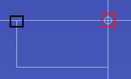
If a closed shape can be created from the current position of the cursor, then a circular mark is displayed on the canvas. This takes account of the Angle lock value. Click this mark to create a point on the cutout. If Angle lock is set to Free, then the circular mark is displayed at angles from the start position which are multiples of 45 degrees. This is illustrated below for the angle of 90 degrees. The start position is highlighted in black.
If a closed shape can be created from the current position of the cursor, then a circular mark is displayed on the canvas. This takes account of the Angle lock value. Click this mark to create a point on the cutout. If Angle lock is set to Free, then the circular mark is displayed at angles from the start position which are multiples of 45 degrees. This is illustrated below for the angle of 90 degrees. The start position is highlighted in black.
Command dialog
Angle lock
| Value | Description |
|---|---|
| 45-degree | The angle (in degrees) between the sides of the figure to be
input is limited to the following values.
|
| 90-degree | The angle between the sides of the figure to be input is limited
to the following values.
|
| Free | The angle between the sides of the figure to be input is not locked. |
Tangent arc
| Value | Description |
|---|---|
| ON | A tangent arc with the radius specified in the Radius of tangent arc field is generated at the corner of a figure. |
| OFF | The vertex is placed at the corner of a figure. |
Radius of tangent arc
| Value | Description |
|---|---|
| Real number greater than 0. | Set the radius of tangent arc to be generated. |
Thermal relief
| Value | Description | |
|---|---|---|
| ON | In the same net as the area fill to be generated, the subtract process is executed on pins, vias, and padstacks in components. This generates thermal lines. | |
| OFF | The subtract process is not executed on pins, vias, and padstacks in components in the same net as the area fill to be generated. | |
| Settings | Displays the Design Settings dialog. This allows you to set the thermal relief values which are shared between multiple commands. |
Subtract parameter
| Value | Description |
|---|---|
| Settings | Displays the Design Settings dialog. This allows you to set the Subtract parameter values which are shared between multiple commands. |
Note
If an area fill shape for a template area is cut into multiple shapes when copper is repoured:
If an area fill shape for a template area is cut into multiple shapes when copper is repoured:
- For the new template areas that are created, the subtract parameter and thermal relief settings used to create them are stored as properties of the template area. You can configure these settings in the Template Parameters dialog.
- If you modify an area fill shape by copying it, or splitting it using the Cutout (Polygon), Cutout (Rectangle) or Cutout (Circle) commands, then the subtract parameters and thermal relief settings that you specify in the command dialog are not applied to the newly-created area fills. Instead, the settings in the Template Parameters dialog are applied.
