
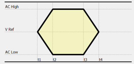
The Mask Editor dialog allows you to create, edit and select masks. Masks are used to check simulation results against relevant targets in the following areas of the application.
- Eye Pattern Analysis
- Impedance Analysis.
Depending on the current operation mode of the Analysis
Result Viewer (Eye Pattern mode or Frequency-Domain mode), the Mask
Editor is opened for the specific type of masks when you click
the open mask dialog button  .
You can select a mask from a list of available masks. These may be stored
in different source locations. You can manage a large number of source
locations and individual mask files. Multiple source locations can be
used to store masks within the file system.
.
You can select a mask from a list of available masks. These may be stored
in different source locations. You can manage a large number of source
locations and individual mask files. Multiple source locations can be
used to store masks within the file system.
For both application areas, the general operation of the Mask
Editor is the same.
Eye Pattern Analysis
Display this dialog by clicking Open
Mask Dialog in Analysis
Result Viewer, when in SI
Eye Pattern mode.
Impedance Analysis
Display this dialog by clicking Open
Mask Dialog in Analysis
Result Viewer, when in Frequency-Domain
mode.
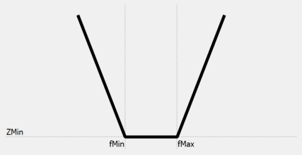
For Power Integrity Impedance analysis purposes, the Impedance masks are used to compare measured or simulated impedance values against a given target impedance mask.
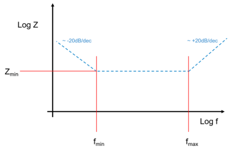
- The Impedance mask definition and plot uses a log/log-scale of the impedance chart.
- You can check an Impedance result Z(f) of the PI Impedance Analysis against a given target impedance profile in the frequency domain.
- Target functions may be derived from data books of IC's or by computing the impedance manually based on an allowed voltage ripple on the supply system.
- It allows the definition of a target impedance ZMin within the given frequency range, between fMin and fMax. Outside of this range, a capacitive or inductive behavior of the target impedance is assumed. This leads to a V-shape, in principle.
- For frequencies lower than fMin the impedance
decreases with -20dB per decade, and for frequencies larger than fMax
the impedance increases with +20dB per decade. This corresponds to
a capacitive and inductive behaviour, as it can be anticipated for
these frequency areas.
One decade is a unit for measuring ratios on a logarithmic scale, with one decade corresponding to a ratio of 10 between two numbers.
The Mask Editor operates in the following modes: View mode and Edit mode.
- In View mode, the Mask Editor allows you to select from a list of existing masks. The management of available mask source folders is possible, but you are prevented from editing masks accidentally.
- In Edit mode, a selected mask can be modified, or a new mask can be created.
When you create a new mask file by clicking the button, the Mask Editor operates in
Edit mode. To open an existing mask
in Edit mode, select it and click the
Edit button in the View
Mask Parameters section.
button, the Mask Editor operates in
Edit mode. To open an existing mask
in Edit mode, select it and click the
Edit button in the View
Mask Parameters section.
The following sections in this dialog are described below. These are numbered in the accompanying image. The procedure for creating masks is also described below.
![]()
![]()
Manage Mask Sources
This section provides a list of all available folders where mask files are stored. It allows you to manage your source locations in the View mode.
- Alias source names are listed here. Typically, these are more readable than actual folder names. The alias source name is defined when you add new folders to the list.
- As a default source location, the folder where the actual simulation result originates from is always available. The name of the data source identifies this location.
| Item | Description |
|---|---|
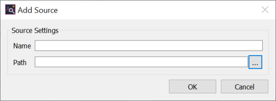
 Add Add |
Allows you to add a source location where mask files are stored.
For example, a company, department or project-specific folder.
Specify the alias name of the source location and its path in
the displayed Add Source dialog.
 |
 Remove Remove |
Removes the selected source location from the Manage Mask Sources table. |

|
Allows you to specify the folders that are used to populate the Mask File table, in the Select/Create Mask File table, by selecting them in this column. |

|
Allows you to define a listed source location as the default save location where the loaded data sources are stored. These include new or edited mask files. Select the required source location in this column. Note
The folder where the loaded data sources are stored is the default folder, if no other source location is selected. Mask files located within this folder can be used without adding the folder as a source location. |
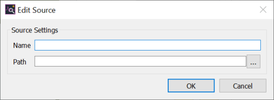
| Source | Displays the alias name that you specify in the Edit Source dialog. Launch this dialog by selecting Edit Source on the assist menu. |
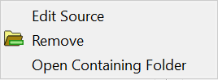
Assist menu
The following commands can be selected on the assist menu by right-clicking a list entry. These are described below.
| Item | Description |
|---|---|
| Edit Source |
Allows you to change the alias name and source path in the displayed Edit Source dialog. The default source location cannot be edited, or permanently removed.
|
| Remove | Deletes the selected source location from the list. |
| Open Containing Folder | Allows you to view the contents of the selected source folder in Windows Explorer. |
Select/Create Mask File
The mask file can be selected from the list of available
mask files in the Select/Create Mask File
section. The mask list shows all mask files contained within the visible
folders, as specified in the  Visibility
column in the source list. Each list entry has a reference to the source
location Src.,
the file base name and its mask type.
Visibility
column in the source list. Each list entry has a reference to the source
location Src.,
the file base name and its mask type.
| Item | Description | |
|---|---|---|
|
New |
Creates a new mask file. The editor on the right side of the dialog is made available in Edit mode. See Editing Masks. | |
 Delete Delete |
Allows you to delete a selected mask file from the folder. A confirmation dialog is displayed. | |
 Standard Filter Standard Filter |
Allows you to filter the contents of the Mask File table to only show Standard Eye masks. This is not available for Impedance Masks. | |
 Setup & Hold Filter Setup & Hold Filter |
Allows you to filter the contents of the Mask File table to only show Setup and Hold Eye masks. This is not available for Impedance Masks. | |
| Filter | Allows you to filter the contents of the Mask File table by entering a value. Only items that contain the specified value are listed in the table. Not available for Impedance Mask. | |
| Mask File table | The selected file content is shown graphically in the View Mask Parameters area, with all used parameters. To modify a parameter, click Edit to select Edit mode. | |
| Src. | Shows the source location of the mask file. This is specified
in the Manage Mask Sources section
by selecting it in the  column.
 |
|
| File | Shows the name that you specify for the mask file in the View Mask Parameters section, File box. | |
| Type | Shows the type of each mask file as either Standard or Setup & Hold for Eye masks, or Impedance for Impedance masks. The Eye mask type is specified in the View Mask Parameters section, Mask Type box. |
View Mask Parameters
This section allows you to edit individual mask parameters by typing in values, or pasting them from an external table.
| Item | Description | |
|---|---|---|
| File |
|
|
| Save
|
When creating a new mask file or editing an existing one, the relevant file is saved in the default save location that you specify. | |
 Save As
|
Allows you to save a mask file with a new name in an accessible folder. This folder is not required to be within the list of source locations. | |
| Edit | Allows you to edit a mask file that you select in the Select/Create Mask File section, Mask File table. The fields in the View Mask Parameters section are made available. If you create a new mask file in the Select/Create Mask File section, then this button is automatically selected. | |
| Cancel | Any unsaved changes that you make in this section are not saved, and the Mask Editor enters View mode. This button is displayed only in Edit mode. | |
| Mask Type | Allows you to specify a Mask Type of Standard or Setup & Hold for Eye masks. Impedance masks are set to Impedance with no selection available. The corresponding mask parameters are listed in the Mask Values box. | |
| Standard | The relevant mask file is assigned the Standard Eye mask type. This is mainly a visual tool to check against given standards. | |
| Setup & Hold | The relevant mask file is assigned the Setup & Hold Eye mask type. These masks are used to derive setup and hold margins as additional measurement values. See the Eye Pattern section for details on the measured values within Eye Patterns. | |
| Units | Allows you to select the units that are used in the Mask Values box for the selected mask file. | |
| ns | Units of nanoseconds are used for the selected Eye mask file. | |
| ps | Units of picoseconds are used for the selected Eye mask file. | |
| V | Units of volts are used for the selected Eye mask file. | |
| mV | Units of millivolts are used for the selected Eye mask file. | |
| MHz | Units of megahertz are used for the selected Impedance mask file. | |
| kHz | Units of kilohertz are used for the selected Impedance mask file. | |
| Ω | Units of ohms are used for the selected Impedance mask file. | |
| mΩ | Units of milliohms are used for the selected Impedance mask file. | |
| Mask Symbol | Displays a graphical representation of the selected mask. If
you change any values in the Mask
Values box, then this image is updated immediately. Example
are shown below for Eye Masks and Impedance Masks.
|
|
| Mask Values | Displays the parameters associated with the mask file that displayed in the File box. In Edit mode, these values can be changed by entering new values. Its associated image is updated immediately in this section. | |
| Comment | In Edit mode, this box allows you to associate a comment with the mask file that is displayed in the File box. |
| Value | Description |
|---|---|
| OK | Assigns the selected mask to the chart area from where the Mask Editor was called. The Eye Pattern Attributes dialog allows you to change the color and line width, for example, of a selected mask. You can also change the horizontal shifting. The OK button is available only in View mode. |
| Cancel | Closes the Mask Editor without assigning the selected mask to the chart area. |
| Help | Launches the Online Help topic for the Mask Editor. |
Editing Masks
The following procedure demonstrates how to edit masks
in the Mask Editor. The View
Mask Parameters section on the right side of the dialog allows
you to edit an existing mask, or create a new one. You can edit these
values only when you select Edit mode
by clicking Edit, or when you create a
new file mask file by clicking  .
This button is shown below.
.
This button is shown below.
![]()
- After clicking ,
Edit mode is automatically selected.
This allows you to create Standard
or Setup & Hold Eye masks or
Impedance masks.
- Enter a file name in the File box.
- After configuring the mask, press Save. The file is saved in the default save location
that you select, and View mode is
selected.
- The assist menu allows you to access various commands. For example, you can edit the contents of the File box in Edit mode. In View mode, you can copy values in the Mask Editor.
The main areas of the dialog are described in the following annotated image.
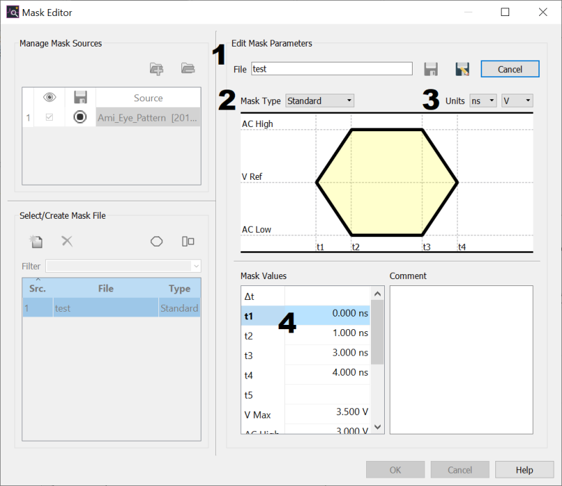
1: Indicates where to define the name of the mask.
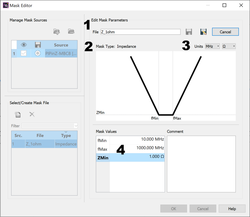
2: Indicates where to choose the mask type. No selection available for Impedance masks.
3: Indicates where to specify the required units.
4: Indicates where to specify the mask parameters.
When an existing mask is selected in the file list, its parameters and associated image are displayed.
- Click the Edit button
to enable Edit mode. To exit Edit mode, click Cancel
or Save. You
cannot close the Mask Editor in
Edit mode.
- View Mask Parameters changes to Edit Mask Parameters and all entry boxes become available.
- Specify a Mask Type of Standard or Setup & Hold for Eye masks. No selection available for Impedance masks.
- The corresponding mask parameters are shown in the Mask Values list.
- Select the Units for the Mask values. For Eye masks, choose the time and voltage units. For impedance masks, choose the frequency and impedance units. The selected units of the Mask Editor are applied to the values.
- Configure individual mask parameters by typing in values. Alternatively, paste in values from an external table, for example, using CTRL+V.
- The mask image is immediately updated when you enter or edit values.
- Alternatively, you can also copy values from an external table using CTRL+C and and past in values using CTRL+V.
- The paste function supports voltage/time and impedance/frequency units, as well as values without units.
- You cannot paste content that is not suitable, such as text.
- Add comments to the mask using the Comment box, if required.
- In Edit mode,
right-click to show the following commands on the assist menu.
- In View mode, only the Copy and Select All commands are available on the assist menu.
- To finish editing or creating a mask, save the
file by clicking Save or
 Save
As. The dialog changes to View
mode.
Save
As. The dialog changes to View
mode. - To discard your changes, click Cancel in the Edit Mask Parameters area of the dialog. Edit mode is exited.
- Click OK to assign the selected mask to the chart area from where the Mask Editor was launched. In Eye Pattern mode, the Eye Pattern Attributes dialog allows you to change the color and line width of a selected mask as well as horizontal shifting.
- Alternatively, click Cancel to close the Mask Editor without assigning the selected mask to the chart area. Note that any file operations that you execute are saved.
- The Dt value is used as a default horizontal offset when displaying the mask within the eye pattern. You can adjust the overall offset in the eye pattern using the Mask Offset field in the Eye Pattern Attribute panel.
- The allowed values for the impedance/frequency input parameters are as follows:
- 1 mΩ < Zmin < 1kΩ
- 1 Hz < fmin < 100 GHz
- 1 Hz < fmax< 100 GHz
- fmax ≥ fmin
